


20
Momentus 5400 FDE Product Manual, Rev. C
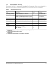
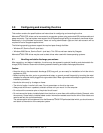
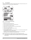
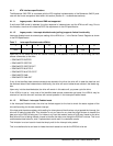
3.2 Jumper settings
3.2.1 Master/slave configuration
Use the options jumper block shown in Figure 6 to configure the drive for operation. This jumper block is the
4-pin header adjacent to pins 1 and 2 of the I/O signal pins. For additional information about using the Cable
select option, see Section 3.2.2.
The “Master or single drive” option is the factory default setting.
Figure 6. Jumper settings
3.2.2 Cable-select option
Computers that use cable select determine the master and slave drives by selecting or deselecting pin 28,
CSEL, on the interface bus. Master and slave drives are determined by their physical position on the cable. To
enable cable select, set a jumper as shown in Figure 6. Refer to your computer manual to determine whether
your computer supports this option.
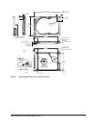
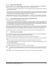
3.3 Drive mounting
You can mount the drive using four screws in the side-mounting holes or four screws in the bottom-mounting
holes. See Figure 7 for drive mounting dimensions (dimensions in inches with mm in parentheses). Follow
these important mounting precautions when mounting the drive:
• Allow a minimum clearance of 0.030 inches (0.76 mm) around the entire perimeter of the drive for cooling.
• Use only M3 x 0.5 mounting screws.
• Do not overtighten the mounting screws (maximum torque: 4.0 inch-lb).
• Four (4) threads (0.080 inches) minimum screw engagement recommended.
Drive is slave
Drive is master (or single drive)
Cable select