


Momentus 5400 FDE Product Manual, Rev. C
25
4.0 ATA interface
These drives use the industry-standard ATA task file interface that supports 16-bit data transfers. It supports
ATA programmed input/output (PIO) modes 0–4 and Ultra DMA modes 0–5. The drive also supports the use of
the IORDY signal to provide reliable high-speed data transfers.
For detailed information about the ATA interface, refer to the draft of AT Attachment with Packet Interface
Extension (ATA/ATAPI-7), NCITS T13, subsequently referred to as the Draft ATA-7 Standard.
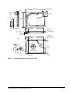
4.1 ATA interface signals and connector pins
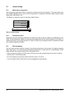
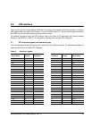
The following table summarizes the signals on the 44-pin ATA interface connector. For a detailed description of
these signals, refer to the Draft ATA-7 Standard.
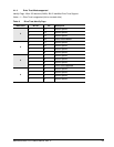
Table 6: Connector signals
Signal Name
Connector
Contact
Cable
Conductor
Cable
Conductor
Connector
Contact
Signal Name
RESET- 1 1 2 2 Ground
DD7 3 3 4 4 DD8
DD6 5 5 6 6 DD9
DD5 7 7 8 8 DD10
DD4 9 9 10 10 DD11
DD3 11 11 12 12 DD12
DD2 13 13 14 14 DD13
DD1 15 15 16 16 DD14
DD0 17 17 18 18 DD15
Ground 19 19 20 20 (keypin)
DMARQ 21 21 22 22 Ground
DIOW- 23 23 24 24 Ground
DIOR- 25 25 26 26 Ground
IORDY 27 27 28 28 PSYNC:CSEL
DMACK- 29 29 30 30 Ground
INTRQ 31 31 32 32 IOCS16-
DA1 33 33 34 34 PDIAG-
DA0 35 35 36 36 DA2
CS1FX- 37 37 38 38 CS3FX-
DASP- 39 39 40 40 Ground
+5 V (Logic) 41 41 42 42 +5V (Motor)
Ground (Return) 43 43 44 44 No connection