


Savvio 10K.2 SAS Product Manual, Rev. D
61
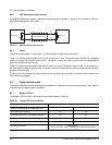
The Ready LED Out signal is designed to pull down the cathode of an LED. The anode is attached to the
proper +3.3 volt supply through an appropriate current limiting resistor. The LED and the current limiting resis-
tor are external to the drive. See Table 25 for the output characteristics of the LED drive signals.
9.5.2 Differential signals
The drive SAS differential signals comply with the intra-enclosure (internal connector) requirements of the SAS
standard.
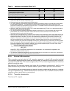
Table 26 defines the general interface characteristics.
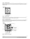
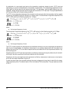
9.5.2.1 Eye masks
9.5.2.1.1 Eye masks overview
The eye masks are graphical representations of the voltage and time limits on the signal at the compliance
point. The time values between X1 and (1 - X1) cover all but 10
-12
of the jitter population. The random content
of the total jitter population has a range of ± 7 standard deviations.
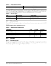
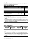
Format in progress, each cylinder change Toggles on/off
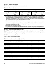
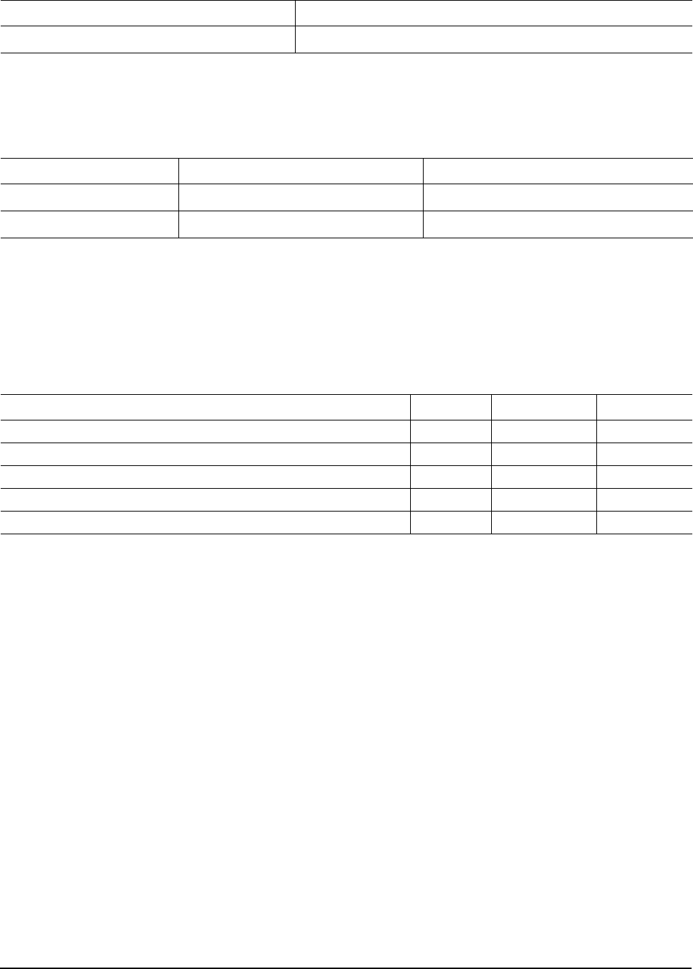
Table 25: LED drive signal
State Test condition Output voltage
LED off, high 0 V ≤ VOH ≤ 3.6 V -100 µA < I
OH
< 100 µA
LED on, low I
OL
= 15 mA 0 ≤ V
OL
≤ 0.225 V
Table 26: General interface characteristics
Characteristic Units 1.5 Gbps 3.0 Gbps
Bit rate (nominal) Mbaud 1,500 3,000
Unit interval (UI)(nominal) ps 666.6 333.3
Impedance (nominal, differential ) ohm 100 100
Transmitter transients, maximum V ± 1.2 ± 1.2
Receiver transients, maximum V ± 1.2 ± 1.2
Table 24: Ready LED Out conditions
Normal command activity LED status