


Pulsar Product Manual, Rev. A 21
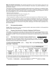
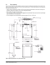
3.4 Drive mounting
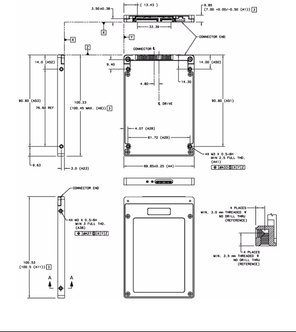
You can mount the drive in any orientation using four screws in the side-mounting holes or four screws in the
bottom-mounting holes. See Figure 3 for drive mounting dimensions. Follow these important mounting precau-
tions when mounting the drive:
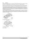
• Allow a minimum clearance of 0.030
in (0.76 mm) around the entire perimeter of the drive for cooling as a
guideline. Please refer to Section 3.5 for final cooling requirements.
• Use only M3 x 0.5 metr
ic mounting screws.
• Four (4) threads (0.080 in) minimum screw engagement recommended. Also ensure maximum screw length
d
oes not bottom out in mounting holes.
• Do not overtighten the mounting screws (maximum torque: 4.5 in-lb, ± 0.45 in-lb).
Figure 3. Mounting dimensions—top, side and end view