


Momentus 5400.3 SATA Product Manual, Rev. C
19
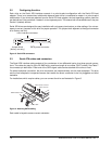
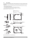
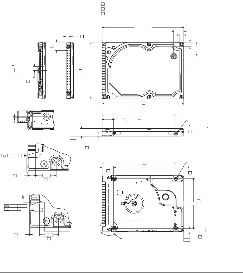
3.4 Drive mounting
You can mount the drive using four screws in the side-mounting holes or four screws in the bottom-mounting
holes. See Figure 4 for drive mounting dimensions. Follow these important mounting precautions when mount-
ing the drive:
• Allow a minimum clearance of 0.030 inches (0.76 mm) around the entire perimeter of the drive for cooling.
• Use only M3 UNC mounting screws.
• Do not overtighten the mounting screws (maximum torque: 4.0 inch-lb).
• Four (4) threads (0.080 inches) minimum screw engagement recommended.
Measurements shown in Figure 4 are in inches.
Figure 4. Mounting dimensions—top, side and end view
BOTH SIDES
2
2
.12 MIN FULL THREAD
2X M3 X 0.5-6H
MOUNTING HOLES; BOTH SIDES
0.148 ±.010 X 90
4X M3 X 0.5-6H
MOUNTING HOLES; BOTH SIDES
.10 MIN FULL THREAD
0.148 ±.010 X 90
1 DIMENSIONS PER EIA-720 OR SFF 8201 SPECIFICATION.
2 DIMENSIONS PER SFF 8212 OR SFF 8223.
3 DRIVE LENGTH W/ PATA IS 3.945±.057 (WORST CASE).
DRIVE LENGTH W/ SATA IS 3.957±.062 (WORST CASE).
1
1
2
(BASE)
(BASE)
BASE
1
1
3
1
(BASE) 1
1
1
1
BASE
2 .152
2 .012
2
(.490 )
(.673 )
-B-
-C-
-D-
.039 B C D
.399
DETAIL A (PATA)
DETAIL A
2.430
.399
.157
2.750 ±.010
3.945 ± .010
.217 ±.050
.217 ±.050
.374 ±.008
2X .118
.551 1
3.567
.551
3.567
.160
DETAIL A (SATA)
.039 B C D
.370
2
.016 C
(.189 )
OF DRIVE
OF CONN.
DATUM B
B
B
(
.020
)
SECTION B-B (SATA)
SATA
PATA
C
C