


MOMENTUS 5400.6 SATA PRODUCT MANUAL, REV. G 22
3.3 SERIAL ATA CABLES AND CONNECTORS
The Serial ATA interface cable consists of four conductors in two differential pairs, plus three ground connections. The cable
size may be 30 to 26 AWG with a maximum length of one meter (39.37 inches). See Table 9 for connector pin definitions.
Either end of the SATA signal cable can be attached to the drive or host.
For direct backplane connection, the drive connectors are inserted directly into the host receptacle. The drive and the host
receptacle incorporate features that enable the direct connection to be hot pluggable and blind mateable.
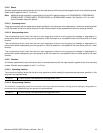
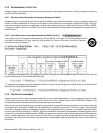
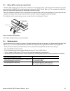
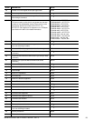
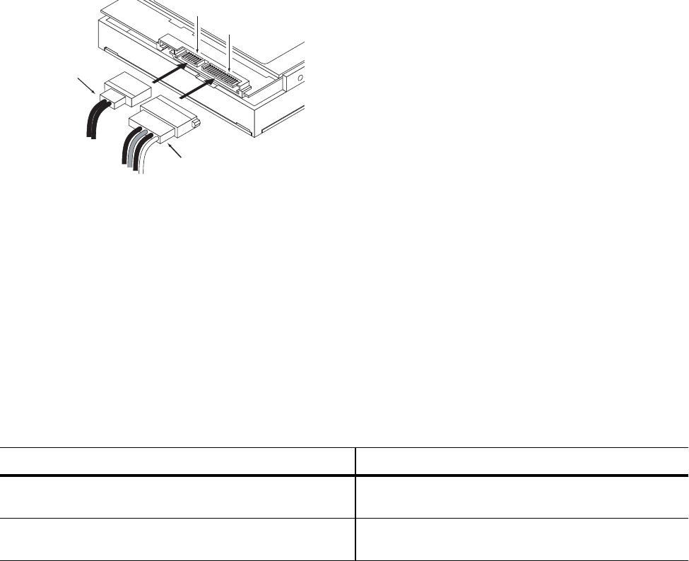
For installations which require cables, you can connect the drive as illustrated in Figure 3.
Figure 3. Attaching SATA cabling
Each cable is keyed to ensure correct orientation.
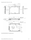
3.4 DRIVE MOUNTING
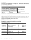
You can mount the drive using four screws in the side-mounting holes or four screws in the bottom-mounting holes. See
Figure Figure 4. for drive mounting dimensions. Follow these important mounting precautions when mounting the drive:
• Allow a minimum clearance of 0.030 inches (0.76 mm) around the entire perimeter of the drive for cooling.
• Use only M3 UNC mounting screws.
• Do not overtighten the mounting screws. Maximum torque: 4.0 inch-lb (0.4519 N-m).
• Four (4) threads (0.080 inches, 2.032 mm) minimum screw engagement recommended.
• Avoid excessive drive distortion when mounting. Refer to the following specifications for stiffness/deflection information:
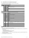
TOP COVER STIFFNESS/DEFLECTION
Operating with no performance degradation, emitted noise,
mechanical damage, or hard errors
10 mm probe: 2.0kgf OR
5 mm probe: 0.92kgf
Non-operating with no hard errors 20 mm probe: 2kgf at any point of top cover
20 mm probe: 15kgf at top cover edges only
Power ca le
inter ace ca le
inter ace connector
Power connector