


4-2
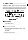
Chapter 4: Name and Function of Each Part
4
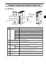
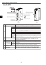
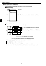
4-2 JW-20FLT
ON
OFF
S
H
I
E
L
D
1Display panel
2Connector for programmer
3Connector for 10BASE-T
6Reset switch
Connector for shield
switch for 10BASE-T
5Module No. switch
(Factory setting: 0)
(Factory setting: ON)
(Front) (Rear)
4
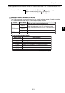
Name Function
1
Display panel Displays the JW-20FLT operating status using LEDs.
LN Lights when communicating normally.
TX Blink at transmitting data.
RX Blink at receiving data.
12 V Cannot be used with the JW-20FLT.
T Lights at test mode. (Normally, this is not used.)
PE Lights at parameter setting error.
HE Lights at this module error.
S0 to S7
Displays the station number when operating normally. Displays an error
code if an error occurs.
2
Connector for programmer
Connect a JW-14PG programmer or similar equipment to set the
parameters on the JW-20FLT.
3
Connector for 10BASE-T Connect the 10BASE-T twisted pair.
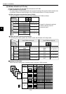
4
Connector for
Shield switch
for 10BASE-T
ON
The shield on the twisted pair cable will be shorted to the FG (base) of
this module.
OFF The shield on the twisted pair cable is not shorted to the base.
5
Module No. switch
Specify a module number from 0 to 6.
-Becareful do not use the same number for another option module.
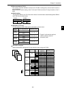
6
Reset switch Only used by SHARP engineers. Users should not press this switch.