


5-6
Chapter 5: Installation
5
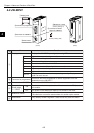
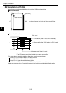
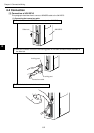
(3) When mounted on Z-511J
The number of boards available mounted on the Z-336J including other communication boards is
two at maximum.
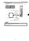
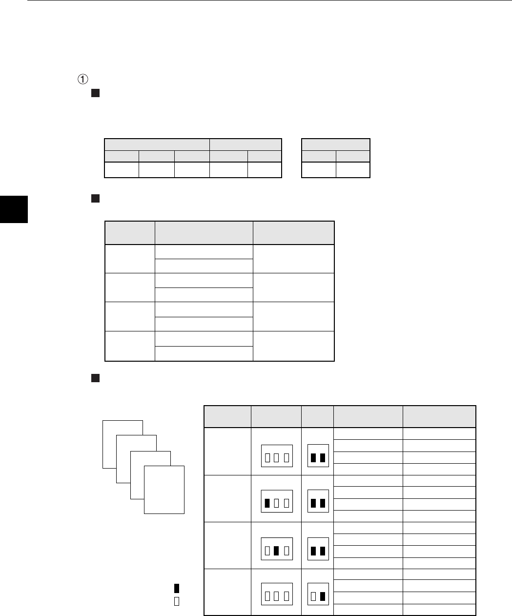
Below shows the switch setting of the Z-511J and Z-336J as well as I/O relay allocation of the Z-
336J.
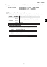
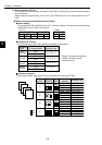
When using one communication board (Z-336J)
Switch setting
The set switches SW1 and SWA on the Z-511J and the number of communication boards setting
switch SWA on the Z-336J are as follows.
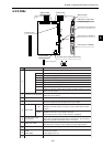
Allocation of I/O relay
I/O relay address of the Z-336J shall be allocated as shown below.
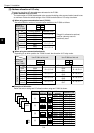
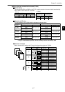
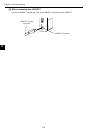
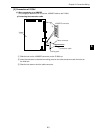
Allocation examples
Below shows switch setting and I/O relay allocation when using one Z-336J.
Z-336J
Z-322J
Z-322J
1
2
3
4
SW1
(RACK NO)
SWA
(SW2)
0000, 0001
0002, 0003
0004, 0005
0006, 0007
0020, 0021
0022, 0023
0024, 0025
0026, 0027
0030, 0031
0032, 0033
0034, 0035
0036, 0037
0010, 0011
0012, 0013
0014, 0015
0016, 0017
R=0, S=0
R=0, S=1
R=0, S=2
R=0, S=3
R=1, S=0
R=1, S=1
R=1, S=2
R=1, S=3
R=2, S=0
R=2, S=1
R=2, S=2
R=2, S=3
R=0, S=4
R=0, S=5
R=0, S=6
R=0, S=7
Z-511J
1
2
3
4
I/O relay
address
Address to set
1 2
1 2 3
1 2
1 2
1 2
1 2 3
1 2 3
1 2 3
SWA
SW2
SW2
SW2
ON
OFF
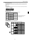
Mounted
position
R = 0, S = 4
R = 0, S = 5
R = 0, S = 6
R = 0, S = 7
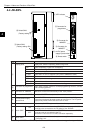
I/O relay address
Address to set
Z-336J
(optional)*
Dummy
(vacant)
Dummy
(vacant)
Dummy
(vacant)
* Though it is allocated as optional,
it will be a dummy area not
functionally used.
0010
0011
0012
0013
0014
0015
0016
0017
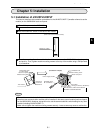
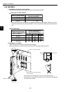
Allocation
details
1 2 3
- Z-511J
1 2
- Z-336J
ON ON
1 2
OFF ON
Switch SWA Switch SWASwitch SW1
OFF OFF OFF