


2
AXT610 ShowLink Access Point
The AXT610 ShowLink™ access point enables real-time remote control of the Axient™ transmitters. The access point allows comprehensive management of transmitter pa-
rameters from the receiver or Wireless Workbench
®
6 using 2.4 GHz wireless network communication. All parameter changes occur without interruption to the performer.
Multiple access points can extend the operational range or increase the number of transmitters supported on the ShowLink network.
Features
• Real-time wireless remote control of up to 16 transmitters per ShowLink access point
• Automated channel selection - Independently scans 2.4 GHz frequency range and determines best channel for use
• Receives power over Ethernet network connection or from an external power supply
• Easy transmitter authentication - Recognizes linked transmitters upon IR sync
• Provides a coverage area equivalent to the range of Axient transmitters
• Automatic hand-offs between multiple access points extend coverage range
• Automatic frequency agility - Moves a ShowLink network to the best available 2.4 GHz channel in the event of signal degradation
• Versatile mounting options - Fits readily available microphone stand adapters and features built-in threading for permanent installation
• Wireless Workbench 6 system supports networked control of all device functions and provides a ShowLink plot for viewing 2.4 GHz signal levels
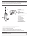
ShowLink Access Point Overview
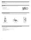
Included Components
Wireless microphone clip for mounting on a microphone stand
WA371
Euro thread adapter for WA371
31A1856
Shielded 25-foot Ethernet cable for ShowLink access point, RJ45-to-EtherCon connector
C825
AXT610
Axient Wireless
Showlink Acces Point
PUSH
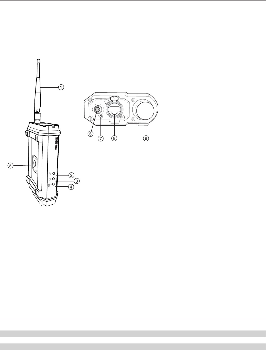
① ShowLink 2.4 GHz detachable antenna
For 2.4 GHz signals
② ShowLink Data Status LED (blue)
• ON Steady: Linked, no data transmission
• Flashing: Transmitting data - rate of flashing indicates level
of activity
③ Power Status LED (green/amber/red)
• Steady Green: Power ON, power source = PoE
• Steady Amber: Power ON, power source = external power
supply
• Red Flashing: Response to remote ID flash command
④ Ethernet Status LED (green)
• ON Steady: Ethernet connected, no traffic
• ON Flashing: Ethernet connected, flashing corresponds to
volume of data traffic
⑤ Threaded mounting point
Use to wall mount the access point
⑥ External power supply connector
Connection point for external power supply
⑦ Reset button
Press to restore factory settings
⑧ Ethernet port
For network connection and Class 1 PoE
⑨ Scanning antenna for channel agility
Scans the 2.4 GHz spectrum for the best frequency