


MP215 Mobile Modem Installation, Configuration, and User’s Guide
PN0000-00 Revision 1.0 05/11/99 3-3
NOTE
The naming convention and signal flow is with respect
to the modem not the PC (host) side. This means that
TXD on the modem side is RXD on the Host Side and
vice versa.
The directions of the arrows indicate signal flow into the
pin or signal flow out of the pin. For example, the pin
labeled TXD has the signal flowing out of the pin and
the arrow pointing away from the pin.
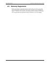
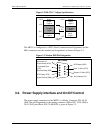
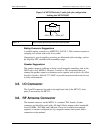
Figure 3-4 Power Connector Pin-out (cable side)
The MP215’s power on/off is controlled by the ignition sense line. When this line
is pulled high (5V - 16 V) the modem will power on. When this line is pulled low
(less than 2 volts) the modem will power off. The modem shuts down (under
software control) when the ignition sense line is pulled low. The modem will
gracefully shut down by de-registering. This avoids potential data loss. This
switch-off process typically takes several seconds to be completed.
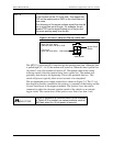
The recommended power supply connection is shown in Figure 3-5: The 12 volt
line should be directly connected to the positive (+) terminal of the battery and the
Ground line directly to the negative terminal. The Ignition Sense line can be
connected to either the electronic ignition switch of the vehicle or an external
toggle switch. The current draw of the ignition sense line is less than 1 mA
CAUTION
Failure to implement a controlled switch off as indicated
in Figure 3-5 (or similar) can cause problems, such as
NEI reset when the 12-volt power is removed.
Connector: 1pc
Molex PN 39-01-2040
Alternate: Molex PN 39-01-2045
Pins: 3 pcs
Molex PN 39-00-0039
Ignition Sense
(White)
Battery (Red)
GND (Black)