


Specifications
Rev 4.0 Oct.09 13
• Power
Interface Port Pin-Outs
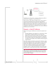
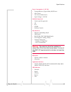
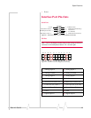
Serial Port
Figure 2-1: Serial Port Diagram: Female DB-9 DCE (not to scale)
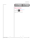
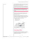
I/O Port
Note: The Pin-Out diagram shows external view looking at PinPoint X
connector in front face-plate of device. Pin 1 is lower right.
.
Figure 2-2: PinPoint X I/O Port Diagram (not to scale)
5
4
3
2
1
9
8
7
6
< - > GND (Ground)
< - DTR Data Terminal Ready)
< - Rx (Receive)
- > Tx (Transmit)
- > DCD (Data Carrier Detect)
Unused
CTS (Clear to Send)
< -
RTS (Request to Send) - >
DSR (Data to Send) < -
1. AnalogInput4 12. AnalogInput3
2. AnalogGround 13. AnalogGround
3. AnalogInput2 14. AnalogInput1
4. NoConnect 15. NoConnect
5. Reservedforfutureuse 16. Reservedforfutureuse
6. Com2(forusewith#7) 17. Com1(forusewith#18)
7. NormalOpenRelay 18. NormalOpenRelay
8. GND 19. GND
9. DigitalInput4 20. DigitalInput3
GND
GND
1
23456
7
891011
12
13141516171819
202122
GND
GND
NC
NC
Rsv
Rsv
AIN3
AIN4
AIN1
AIN2
DIN1
DIN2
DIN3
DIN4
Relay 1
Relay 2
Com2
Com1
NO2
NO1
GND
GND