


16
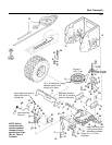
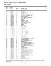
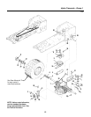
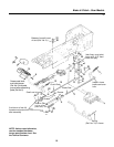
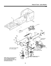
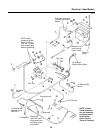
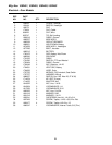
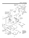
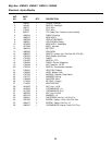
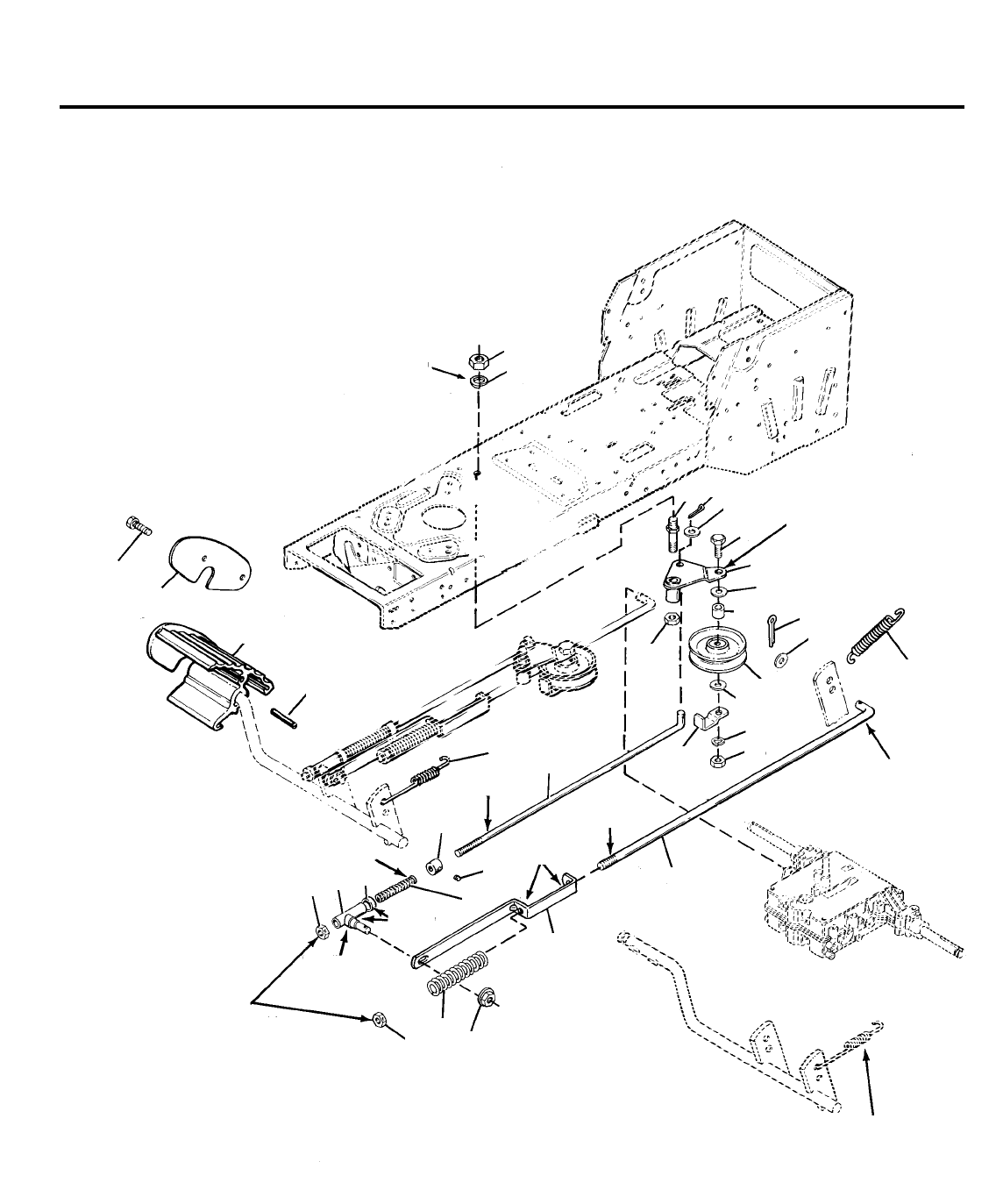
Brake & Clutch - Gear Models
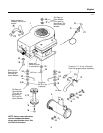
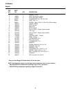
NOTE: Unless noted otherwise,
use the standard hardware
torque specification chart. See
the Table of Contents.
**50
Between frame & head
of stud (Ref. No. 2)
21
20
2
22
23
25
26
4
14
22
23
10
28
19
18
13
27
15
12
32
30
1
9
31
16
24
11
17
7
24
3
Idler Assy. must pivot
freely with .015" maxi-
mum end play.
Clutch Rod
Grease
Grease
Brake Rod
A minimum of two full
threads must extend thru nut
after assembly
8
5
6
29
Install in uper
hole on clutch
pedal assy. arm.
Install in lower
brake cam lever
hole.
Grease pedal shaft
and insert damper
(Ref. No. 8) into pedal
groove before assembling
pedal (Ref. No 5).
Small end of spring
Spring
(Ref. No. 12) in frame