


20
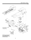
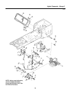
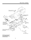
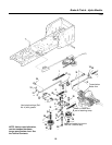
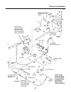
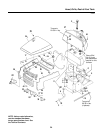
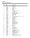
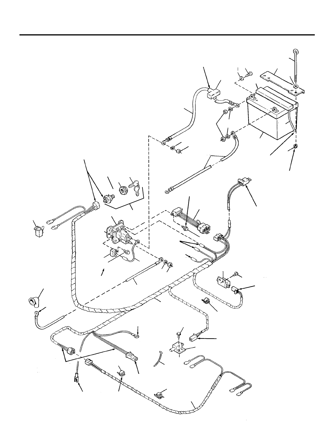
Electrical - Gear Models
NOTE: Unless
noted otherwise,
use the standard
hardware torque
specification
chart. See the
Table of Contents.
**2413
14
31
10
20
27
28
13
18
22
34
17
35
3
35
23
16
34
9
8
16
2
26
24
25
17
6
4
11
5
1
29
30
29
7
19
21
33
12
Slide boot over termi-
nal after securing to
battery.
Place end of
hose through
hole in frame.
Mount in
frame
To Operator
Present Seat Switch
Zinc. Pltd.
To Neutral Start
Switch
To PTO Switch
Engine ground
To Alternator
Mounts to
lower RH hood
hinge away from
pivot pinch point
and muffler
To Magneto.
Tie wrap wires
together using
Ref. No. 6
To Starter
Motor
Zinc Pltd.
NOTE: Apply
grease to ignition
switch terminals
(Ref. No. 14) and
wire harness plug
before connecting.
32
30
36