


4
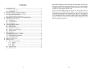
Contents
1. INTRODUCTION .............................................................................. 5
1.1 General Description ..............................................................................5
1.2. Specifications........................................................................................5
2. DISPLAY AND KEYPAD CONTROLS............................................... 6
3. INSTALLATION AND PANEL CUTOUT ............................................. 6
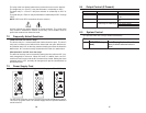
3.1 Mounting Requirements .......................................................................6
3.2 Engineering Label Placement ..............................................................7
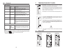
4. REMOVING / INSTALLING OPTION MODULES .............................. 7
5. OPERATING THE KEYS................................................................... 8
5.1 In Run Mode .........................................................................................8
5.2 In Program Mode ..................................................................................8
5.3 In Edit Mode..........................................................................................8
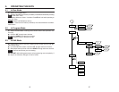
6. PROGRAMMING MENU...................................................................9
6.1 Relay Control ........................................................................................9
6.2 Display Control ...................................................................................10
6.3 Measurement Control .........................................................................10
6.4 Output Control (If Present)..................................................................11
6.5 System Control ...................................................................................11
6.6 Password ............................................................................................12
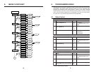
7. TEMPERATURE INPUT CARDS .................................................... 13
7.1 Relay Cards ........................................................................................13
7.2 Frequently Asked Questions...............................................................14
7.3 Power Supply Card .............................................................................14
8. MENU FLOWCHART ...................................................................... 16
9. MENU DETAIL ................................................................................ 18
9.1 Relay Control (Sp1-Sp4).....................................................................18
9.1.1 Response .............................................................................................. 18
9.1.2 Delay ..................................................................................................... 18
9.1.3 Latch ..................................................................................................... 19
9.1.4 Alarm..................................................................................................... 19
9.2 Display Control ...................................................................................19
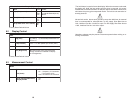
9.3 Output Control ....................................................................................20
21
20mA) When the display reaches 0 percent the analog output would be 4mA.
The limits can be moved or reversed (HI=0 and LO= 80.0), in this case when
the display reads 0 , the analog output would be 20mA and when the display
reads 80, the analog output would be 4mA.
The Fail Safe option (FS) controls the action of the analog output when the
display goes into over-range (EEEE or –EEEE). In some cases, the low limit
or high limit are reserved for error conditions. With set to ‘HI’, the output will
run to the 20mA value when over-range or under-range occur. With failsafe set
to ‘LO’, the output will run to 4mA at over-range or under-range. With failsafe
‘Off’, the output will go to the defined limit ends. (-EEEE would be 4mA and
EEEE would be 20mA typically.)