


7
4.
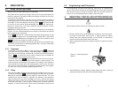
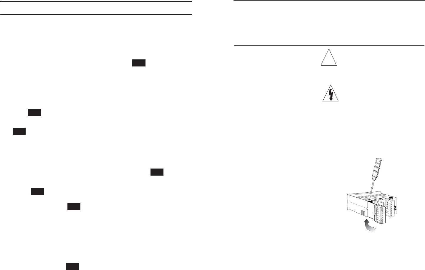
REMOVING / INSTALLING OPTION MODULES
Shut off power before removing or installing any option module.
1. Remove module from case by inserting a screwdriver into tab slot open-
ing at top of input module (see Figure 5-1). Apply pressure to release
module from case. Repeat procedure for tab located on underside of
module and then slide module away from case.
2. Refer to appropriate sections to configure switches or jumpers for proper
operation.
!
3. Install module by carefully aligning module edges with slots in case and
pressing forward until tabs (on top and bottom) engage.
Figure 5-1. Removing Option
Module
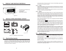
3.2 Engineering Label Placement
If the engineering unit label needs replacing, place the tip of a ballpoint pen
into the small hole at the base of the engineering label in the bezel. Slide the
label up until it pops out. Grasp and remove. Slide the new label half the dis-
tance in, then use the ballpoint pen to slide it down into place.
18
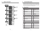
Press RE to choose Val-1 as the setting to be edited. Notice that the far right
digit has an alternating cursor. To change this digit, use S or T. To move to the
next digit, press W. When all changes to the value are complete, press
RE to confirm the change and save it to memory.
NOTE: Any power loss before confirming a change will lose the edited value.
The menu will revert back to alternating between Val-1 and value. Press T to
move to the response setting.
9.1.1 Response
The display will now show “Rsp.” To edit response, press RE , otherwise
press T to move to the next choice. When editing Rsp., the display will show
Hyst, Dlay, or Ltch Flashing. Use S or T to choose the required response.
Press RE to confirm the choice. When choosing Hyst, the display will
alternate between Hyst and the current value.
To edit the value, press RE . Otherwise press T to move to the next choice.
Hysteresis will be used above and below the setpoint in equal amounts. The
value represents a percentage of the setpoint. For example: If the setpoint is
set to 100.00 with a high alarm and therhysteresis is set for 8.5%, the alarm
will not turn on until the reading on the display reaches 108.50. Once tripped,
the alarm will not turn off until the display reaches 91.50.
9.1.2 Delay
When choosing Dlay, the display will alternate between Dlay and current value.
To edit the value press RE . Otherwise press q to move to the next choice.
Dlay will be used above and below the setpoint in equal amounts. The value
represents the amount of delay in seconds. For example, if the setpoint is
again configured for high alarm and Dlay is set for 2.5 seconds the display
crosses the setpoint value and a timer begins to count off the 2.5 seconds
before the alarm trips. If, during those 2.5 seconds the value falls below the
setpoint, no action will be taken. When the unit successfully counts off 2.5
RESET
ENTER
RESET
ENTER
RESET
ENTER
RESET
ENTER
RESET
ENTER
RESET
ENTER
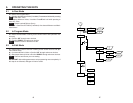
9. MENU DETAIL
9.1 Relay Control (Sp1-Sp4)
While in menu, all other operations are suspended.
The H340 has four setpoint parameters and up to four relays associated with
those four setpoints. The setpoint LEDs on the display will light even if no relay
is present for that setpoint.
To change the setpoint value, enter the menu by pressing W. If the password
allows relay control, it will be the first menu to appear. The display will show the
word “Sp1”. If this is the setpoint to be edited, press RE , otherwise press T
to move to the next choice. When editing Sp1, the display will alternate be-
tween Val-1 and a value. The “value” represents a threshold above or below
the setpoint being set to alarm.
NOTE: Before editing this value, be sure that the decimal point is in the proper
position. It is also recommended that any scaling or linearization be entered
before setpoints are determined.
RESET
ENTER