


April 17, 2000 Manual Version 1.0
3.10
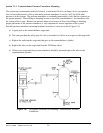
NOTE: The cable should remain unbroken except for the connector in this junction box to
keep the shield integrity - do not splice the cable!
c) The slide should travel no more than 1 inch per turn of the resolver.
d) The cable from the resolver to the OmniLink 5000 should not be run with any high voltage
wiring (i.e. 120/240 VAC). In fact, this cable should be run in its own shielded conduit.
It is not necessary to know the exact gear ratio of slide travel to resolver turns - only that conditions “b”
and “c” are met. The resolver may rotate in either direction relative to slide travel (i.e. the resolver may
rotate clockwise or counter-clockwise as the slide goes down).
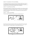
Section 3.6.2 Rotary Slide Adjust Wiring
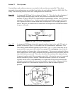
A cable must go from the dual resolver mounted on the slide to the auto-setup board in the OmniLink
5000 extended card rack. Since the slide goes up and down relative to the machine, some means of
stress relief must be used on the cable between the slide and the machine frame. The recommended
method is to use a helical cable (same principle as a telephone handset cord) from the resolver to a
junction box on the bottom of the crown. This lets the wire run in a “spring” pattern to help it resist
breaking. Appendix B, Figure B.3 shows a conceptual view of this type of resolver mounting. The
junction box should be grounded to the machine to help shield the connections inside.
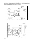
Slide adjust motor starters with and without auxiliary contactors are supported. Solenoid air valves for
air motors are also supported. Refer to Appendix B for typical wiring diagrams. Figures B.4 and B.5
show the wiring for two supported dual resolvers. Figures B.9 and B.10 show the wiring of slide adjust
motor starters with and without auxiliary contactors. Figure B.11 shows the wiring of a slide adjust air
motor. If an OmniLink 5000 control is ordered with a slide adjust system, then a wiring diagram will be
provided as part of the documentation package.
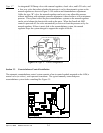
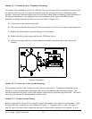
Section 3.6.3 Linear Transducer Mounting
Linear shut height control makes use of linear magnetostrictive transducers. These transducers have a
head that contains the electronics and a guide tube from 6" to 48" in length depending on the application.
The guide tube is mounted to pass through (without touching) a separately mounted annular (doughnut
shaped) magnet. The electronics sense the magnet location as the magnet moves up or down the guide
tube when the slide is adjusted to provide shut height distance to the OmniLink 5000 control.
To install the linear transducer, there must be some point on the slide assembly that moves up and down
with respect to a fixed point on the slide assembly when the shut height is changed. The transducer
should be mounted to one point and the magnet to the other with strong, rigid, brackets. The particulars
of mounting a linear transducer may vary greatly from press to press but keep in mind the following
points:
a) Make sure there is adequate clearance from the transducer to the crown or other possible
interference points of the press. A common mistake is mounting the transducer with the slide
lowered and crushing the transducer when the slide is raised.