


April 17, 2000 Manual Version 1.0
4.10
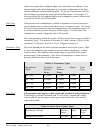
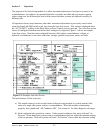
Lock Time Most slide adjust systems now use an integrated brake built in to the slide adjust
motor that automatically locks the system down when the slide adjust motor is not
on. “Lock Time” is used only for slide adjust systems that have a separate
locking system that must be disengaged before the slide adjust motor is engaged.
The lock time is the amount of time the system will wait before energizing the
slide adjust motor after unlocking the system to prevent the slide adjust motor
from trying to run before the lock fully releases.
Section 4.2.2.1 Calibrating Linear Slide Adjust Systems
After setting the parameters in the previous section, the linear slide system must be calibrated before it
can be used.
WARNING! Since the slide adjust configuration procedure requires measurement of
the space between the press slide and bed or bolster, this procedure must
be performed with no dies or tooling in the press to prevent the
possibility of a point of operation or pinch point injury to personnel
making the measurement. Failure to heed this warning may result in
serious injury or death.
IMPORTANT! Configuring/calibrating the slide adjust module should only be done with no
dies installed in the press and, for presses equipped with slide counterbalance
systems, should proceed only after the counterbalance is properly adjusted to
offset the weight of the slide. If counterbalance pressure is too low, bearing
clearances will cause shut height measurements made during calibration to be
too small.
To calibrate a linear slide adjust system:
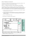
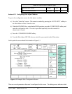
a) Make sure the upper and lower limit settings have been set correctly in the slide configuration
screen of Figure 4.3.
b) Press the “CALIBRATE SLIDE” softkey in the slide configuration screen of Figure 4.3.
c) A screen will appear with a warning that calibrating the slide should not be undertaken without
first reading this manual. Press the “CONTINUE SLIDE CAL.” softkey to continue the
calibration process or “EXIT” to return to slide configuration.
d) The “orientation” of the linear transducer must now be set. This should be set to 0 if the magnet
moves toward the control head (where the transducer cable plugs in) of the transducer when the
slide is going up. Use 1 if the magnet travels toward the control head when the slide is going
down. Press the “CONTINUE SLIDE CAL.” softkey to continue the calibration process or
“EXIT” to return to slide configuration.
e) The “wire speed” (if a GEMCO linear transducer is used) or the “gradient” ( if an MTS linear