


18 19
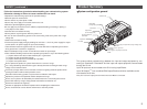
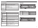
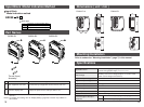
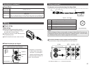
Input Block Model Indication Method
EX250 IE
Block type
1
2
3
Input points : 2, M12 connector (2pcs.)
Input points : 4, M12 connector (2pcs.)
Input points : 4, M8 connector (4pcs.)
Input Block
Model indication method
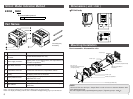
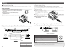
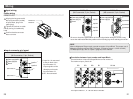
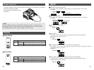
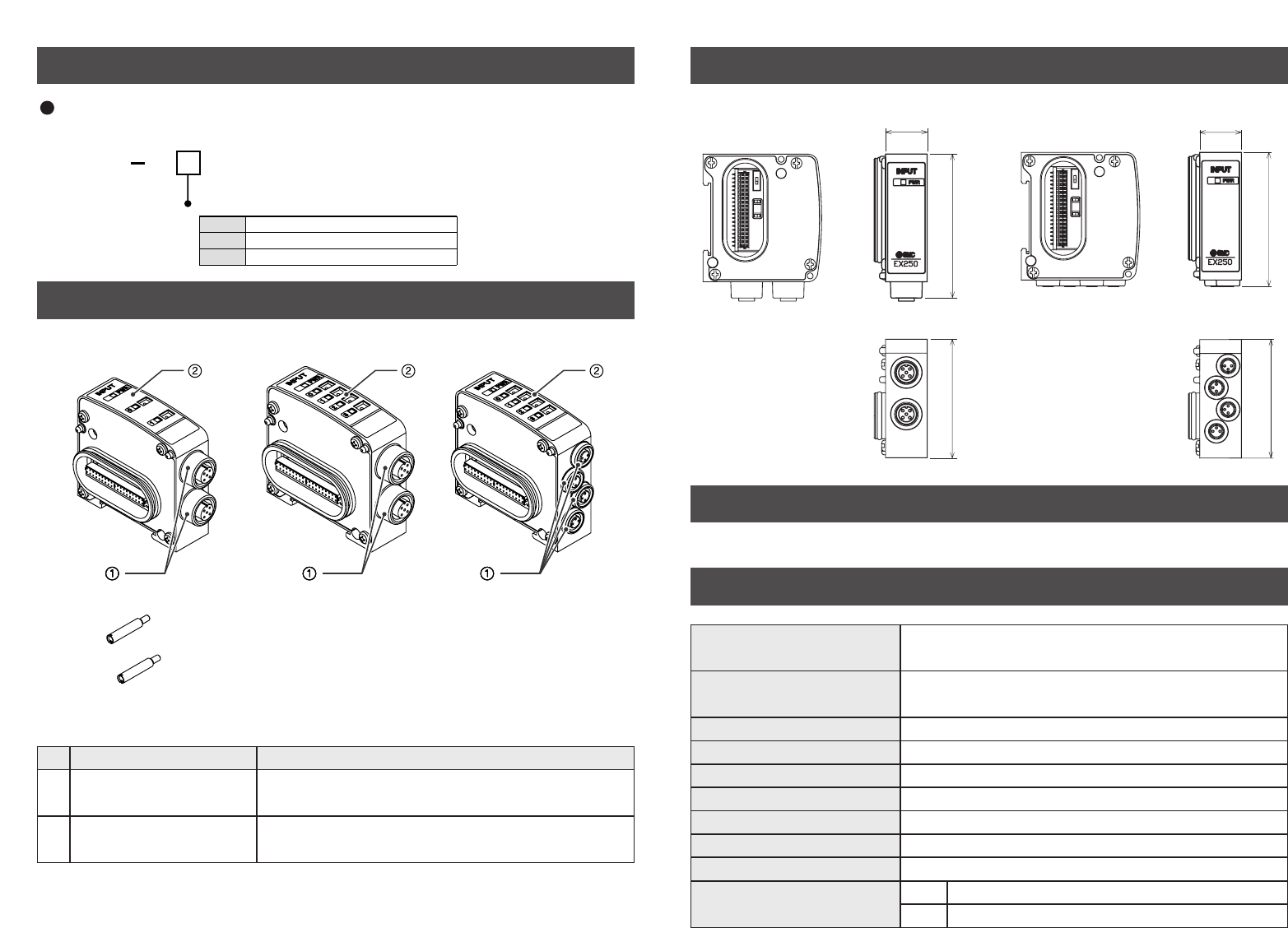
Part Names
No.
Part names Application
1 Input equipment connector Connects the input equipment such as sensor, etc.
Note1
2 Operation display LED Displays the power source and input status.
Note2
EX250-IE1 EX250-IE2 EX250-IE3
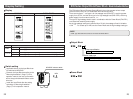
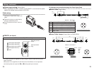
Tie-rod (2 pcs.)
Accessory
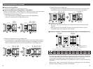
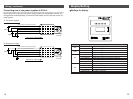
Dimensions ( unit : mm )
59.8 72.6
21
59.8 67.4
21
EX250-IE1/2 EX250-IE3
Mounting/Installation
Refer to subsection "Mounting/Installation" (page 7) in this manual.
Specifications
Applicable sensor
Current source type(PNP input)
Current sink type(NPN input)
*Selected with a switch.
Rated voltage
24VDC (It can have a voltage drop for 1V at max. to the
power source voltage of the SI Unit.)
Logical "1" input voltage VH 11 to 30V
Logical "0" input voltage VL -3 to +5V
Logical "1" input current IH 8mA Typ.
Connection of 2-wire sensor Possible
Logical "1" input current IL Max.2.5mA
Input delay time 3msec. Typ.
Supply current to sensor Max. 120mA / Input Block
Note1 : For wiring method, refer to subsection "Wiring" (page 20) of section "Input Block" in this
manual.
Note2 : For display and setting, refer to "Display/Setting" (page 22) in section "Input Block" in
this manual.
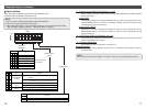
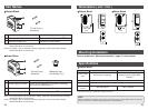
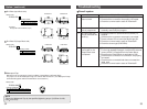
Connector type of the input
equipment
IE1/2
IE3
M12 connector (4 pin, plug or 5 pin, plug)
M8 connector (3 pin, plug)