


20 21
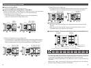
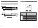
Wiring
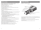
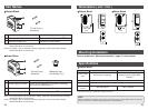
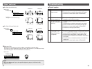
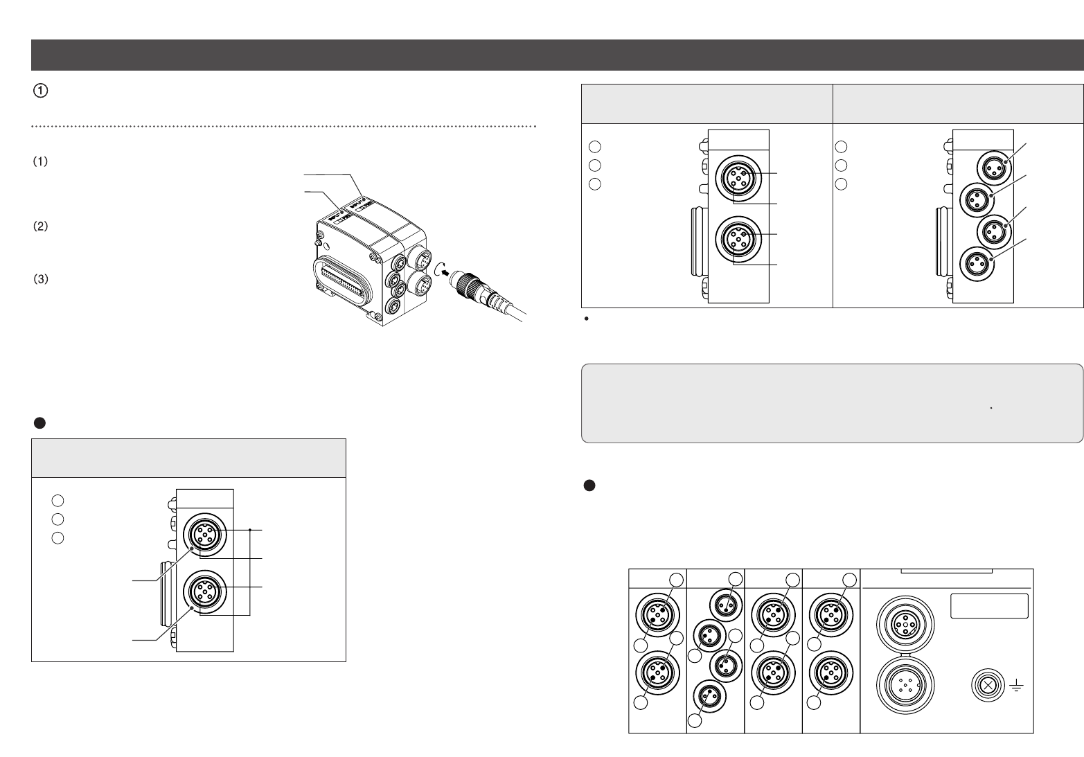
EX250-IE3
EX250-IE1/2
EX250-IE1
(M12 connector, 5 pin, Socket)
EX250-IE2
(M12 connector, 5 pin, Socket)
*1) Input No.1 is connected
to the pin No.2 of the
input connector "0",
2 input signals can be
directly input from the
input connector "0".
*2) NC : Not connected
EX250-IE3
(M8 connector, 3 pin, Socket)
1
1
2
2
3
3
4
4
5
5
5
5
1
1
4
4
3
3
2
2
Input No.1
*1
Input No.0
NC
*2
1
Power supply (24VDC)
3
Power supply (0V)
5
Ground
Input connector "0"
Input connector "1"
4
4
1
1
4
4
1
1
2
2
3
3
2
2
3
3
5
5
5
5
Input No.1
Input No.0
Input No.3
Input No.2
1
Power supply (24VDC)
3
Power supply (0V)
5
Ground
1
1
3
3
4
4
1
1
4
4
3
3
1
1
4
4
3
3
1
1
4
4
3
3
1
Power supply (24VDC)
3
Power supply (0V)
4
Input connector
Input connector
Input connector
Input connector
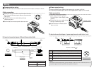
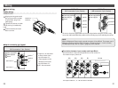
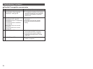
Be sure to check the specifications of the input signal when wiring the sensor.It may
cause the malfunction.Mind the position of the mounting key when selecting the sensor.
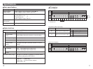
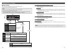
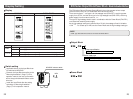
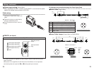
Correlation between input number and Input Block
The total number of Input and Output Blocks can not exceed 10.
The maximum input point is 32.
The input number is 1, 2 ...32 from the SI Unit side.
BUS
BUS
PWR
PWR
SI Unit
IE2
IE1
IE2
IE3
11
11
13
13
10
10
12
12
1
1
0
0
1
1
3
3
5
5
2
2
4
4
6
6
8
8
7
7
9
9
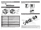
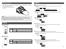
Aligning the key groove with
the input connector (socket)
of Input Block, plug in the
cable (plug).
Tighten the lock nut on cable
side by turning it clockwise by
hand.
Confirm that the connector
does not move.
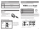
EX250-IE1/2/3
Input wiring
Cable wiring
Input connector pin layout
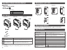
NOTE
Mount a Waterproof Cap on each unused connector of Input Block. The proper use of
Waterproof Cap can achieve IP67 Enclosure. (Tightening torque : 0.1N m for M12)
For Waterproof Cap, refer to "Option" (page 32) in this manual.