


6 7
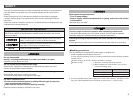
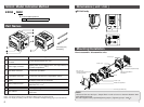
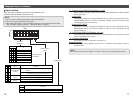
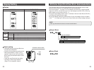
SI Unit Model Indication Method
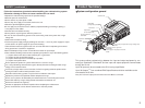
Tie-rod (2 pcs.)
Accessory
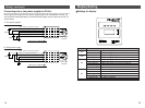
Note1 : For wiring method, refer to subsection "Wiring" (page 12) in this manual.
Note2 : For display and setting method, refer to subsection "Display/Setting" (page 15) in this manual.
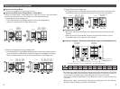
Dimensions ( unit : mm )
BUSBUS
PWRPWR
SOLSOL
NSNS
PWRPWR
SETTINGSSETTINGS
11
00
MSMS
-- -- -- -- --
64.459.8
63
78.9
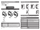
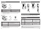
No.
Part names Application
1
Communication
connector
Connect with EtherNet/IP line.
Note1)
2 Power supply connector
Supplies power to the solenoid valve, the Output Block, SI
Unit and the Input Block.
Note1)
3 Input Block connector Connects the Input Block.
4 Output Block connector Connects the solenoid valve, Output Block and etc.
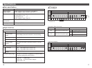
5 Display LED display shows the SI Unit status.
Note2)
6 Switch protective cover
Display the power supply status and communication
status with PLC.
Note2)
7 Ground terminal Used for grounding.
8
MAC address
A unique MAC address of 12 hexadecimal number digits to
each SI Unit.
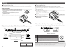
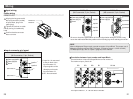
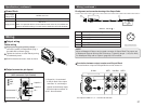
Tie-rod : 2 pcs.
Tie-rod : 2 pcs.
Tie-rod : 2 pcs.
EX250 series Input Block
End Plate (Input Block side)
SI Unit
EX9 series Output Block or
Power Block
Solenoid valve or
End Plate R (Output Block side)
M3 x 18 : 2 pcs.
(Hexagon socket head cap screw
(with spring washer))
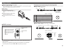
Mounting/Installation
How to assemble / disassemble units.
NOTE
Hold the SI Unit and the Input / Output Block in order to have no clearance between them
while tightening the bolt.
Be sure to tighten bolt by specified tightening torque. (Tightening torque : 0.6N m)
SI Unit body
Part Names
EX250 SEN1
Communication protocol
EN1
EtherNet/IP