


12 13
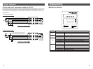
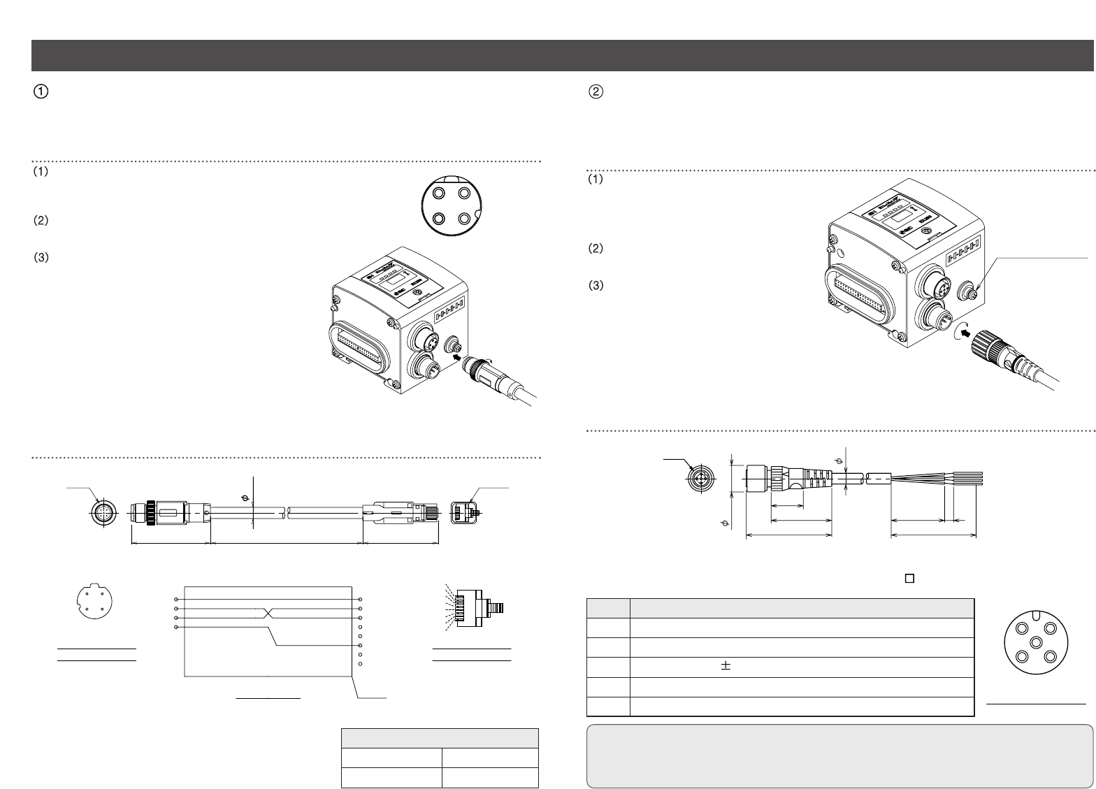
Wiring
43
21
1
34
2
M12
1
2+Rx
3
-
Tx
4
-
Rx
1
2
3
4
5
6
7
8
Shield
RJ45
6.7
47.3 452000
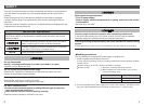
Model No. : EX9-AC020EN-PSRJ
+Tx
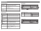
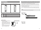
Wiring diagram
Cable core wire external color
Terminal No.
Pin assignment of
plug connector
Pin assignment of
plug connector
White/Orange
Orange
White/Green
Green
8
7
6
5
4
3
2
1
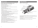
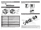
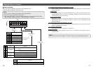
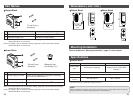
Connect the Power Supply Cable to the power supply connector of SI Unit.
When selecting the power supply, refer to "Handling precautions" (page 3) in this manual.
M3 Earth terminal
Socket connector pin layout
Model No. : EX500-AP -S
M12
14.9
48
34
18
6
30 5
50
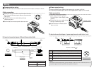
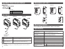
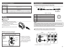
Communication wiring
Connect the Ethernet Communication Cable to the communication connector of SI Unit.
Cable connection
Aligning the key groove with the communication connector
(4-pin, socket) of SI Unit, plug the Ethernet Communication
Cable (plug).
Tighten the lock nut on cable side by turning it
clockwise by hand.
Confirm that the connector portion does not move.
Pin layout and connection diagram of Ethernet Communication Cable
Core wire
Sheath color
Cable specifications
AWG 26
Blue green
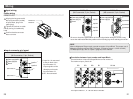
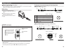
Power supply wiring
Cable connection
Aligning the key groove with the
power supply connector (plug) of
SI Unit, plug the Power Supply Cable
(socket).
Tighten the lock nut on cable side by
turning it clockwise by hand.
Confirm that the connector portion
does not move.
Pin layout and connection diagram of power supply connector cable for (unit : mm)
Pin No.
5
4
3
2
1
Cable color: Signal name
Brown : 24VDC +10%/-5% (for solenoid valves/output)
White : 0V (for solenoid valves/output)
Blue : 24VDC 10% (for input and control)
Black : 0V (for input and control)
Grey : Earth
NOTE
Ground the Earth terminal with the ground resistance at 100 ohm or less. Make the pin No.5 of
the power supply connector ungrounded, and ground at one point.