


28 29
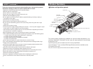
Wiring ( continued )
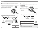
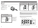
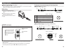
M12 connector, 5 pin, Reverse key
1
Power supply for output (24VDC)
2
Power supply for output (0VDC)
5
Ground
( 3
Power supply for sensor (24VDC))
*
( 4
Power supply for sensor (0V))
*
4
4
1
1
4
4
1
1
2
2
3
3
2
2
3
3
5
5
5
5
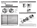
Power supply connector
(Socket)
Power input connector
(Plug)
*
It is used when power is supplied to SI Unit, using an exclusive cable from the power
supply connector.
When power is not supplied to the SI Unit from the Power Block, it is not required to
connect the power to the pins No. and of the power input connector.
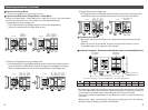
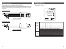
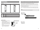
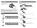
Pin alignment and connection drawing of the Power Supply Cable
Socket connector pin layput ( Reverse key )
Model No. : EX9-AC -1
M12
6.4
30 5
50
48.1
Power Cable (Power Block)
Socket connector pin layout
Model No. : EX9-AC002-3
6.4
48.152
200
M12 M12
Power Cable Jumper (Power Block to EX250-SEN1)
Plug connector pin layput ( Reverse key )
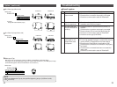
Wiring diagram
Cable color
Brown
White
Blue
Black
Grey
1
2
3
4
5
1
2
3
4
5
Terminal No. Terminal No.
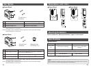
Cable wiring
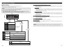
Aligning the key groove with the
connector of Power Block, plug in the
cable.
Tighten the lock nut on cable side by
turning it clockwise by hand.
Confirm that the connector does not
move.
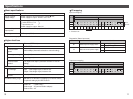
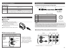
EX9-PE1 pin layout
Pin No
5
4
3
2
1
Cable color: Signal name
Brown : Power supply for output (24VDC)
White : Power supply for output (0V)
Blue : (
Power supply to sensor (
24VDC)
)
Black :(
Power supply to sensor (0V))
Grey :
Earth
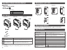
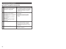
Power supply wiring (Power Block)
When operating EX9-OEP1, combine it with EX9-PE1, and connect the power
supply to the power input connector of EX9-PE1.