


4 5
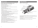
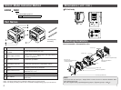
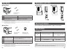
Product Summary
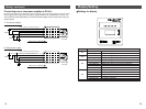
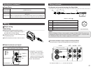
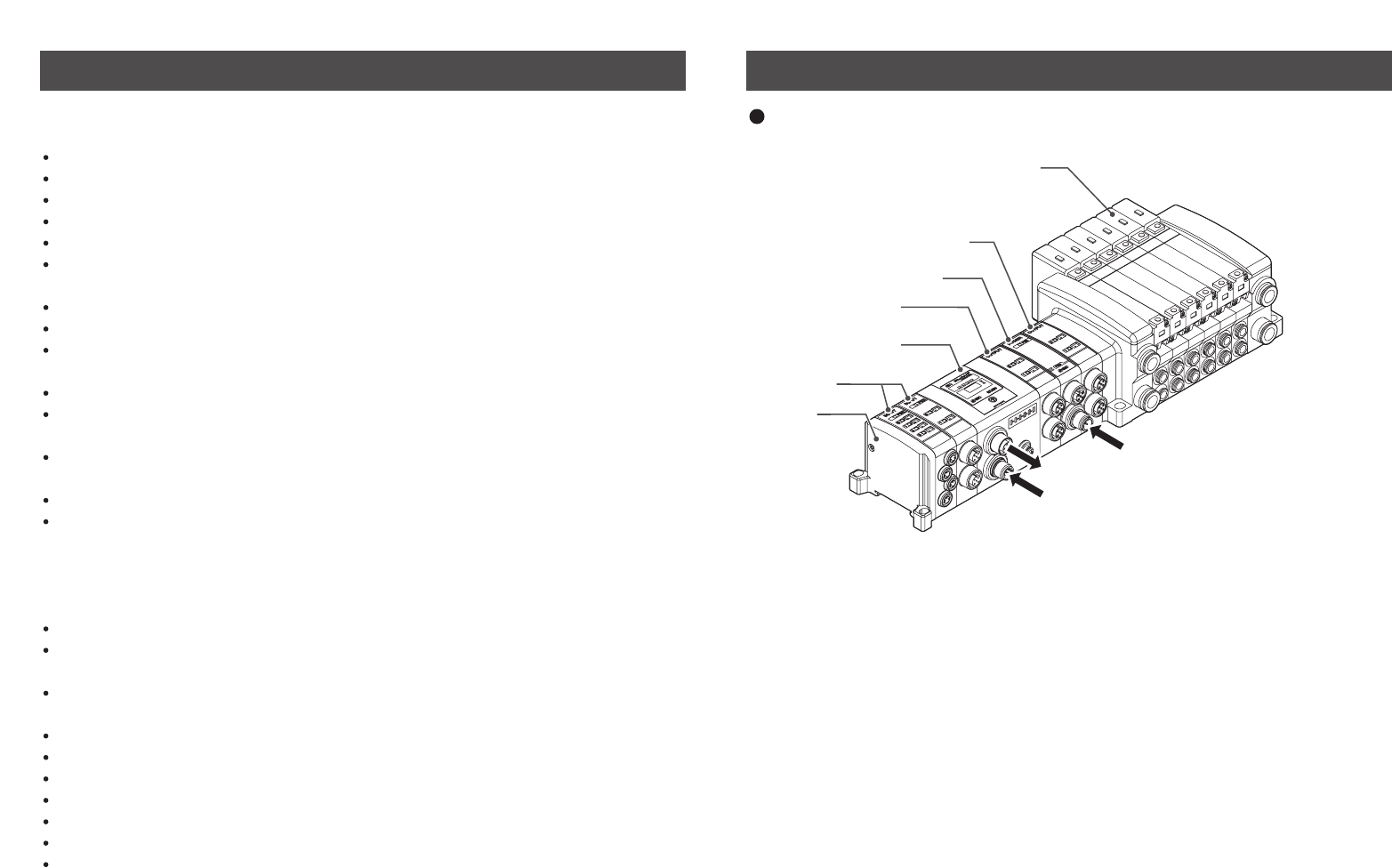
Power supply for Output Block (for high wattage load)
24VDC
Connecting to bus at upper level
(EtherNet/IP)
Power supply for output/input and control
24VDC
Solenoid valve
Output Block
(for high wattage load)
Power Block
Output Block
(for low wattage load)
SI Unit applicable to
EtherNet/IP
Input Block
End Plate
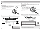
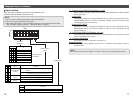
This system realizes reduced wiring between the input and output equipment by con-
necting to EtherNet/IP. EtherNet/IP and the input and output equipment communicates
through the SI Unit.
Up to 32 Inputs can be connected to the SI Unit using Input Blocks.
Up to 32 Outputs
Note)
from combined EX9 Output Blocks and Valve manifolds can be
connected to the SI Unit.
Note) The maximum output point is 24 when the Power Block is connected.
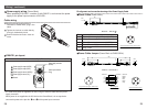
SAFETY ( continued )
Follow the instructions given below when handling your reduced wiring system.
Otherwise a damage or failure to cause a malfunction can result.
Operate the reduced wiring system at the specified voltage.
Reserve space for maintenance.
Do not remove any name plate or label.
Do not drop, hit or apply an excessive shock to the unit.
Follow the specified tightening torque.
Do not apply any excessive force to cables by repeated bending, tensioning or placing a
heavy object on the cables.
Connect wires and cables correctly.
Do not perform any wiring work while the power is on.
Do not use the reduced wiring system on the same wiring route as the power line or high
voltage line.
Confirm the insulation of wiring.
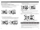
Perform the power supply wiring by dividing into two lines ---- one is for power supply for output
and the other is for power supply for input and controlling.
Take sufficient measures against noise such as noise filter when incorporating the reduced
wiring system into a machine or equipment.
Mount a Waterproof Cap on each unused M12 connector for input/output.
Take sufficient shielding measures when operating the product in any of the following places.
( 1 ) A place where noise due to static electricity etc. is generated
( 2 ) A place of high electric field strength
( 3 ) A place where exposure to radioactivity is possible
( 4 ) A place near power cable
Do not operate the product in a place where there is a source of surge.
Use a surge absorbing element built-in type to directly drive the load that generates surge
voltage such as solenoid valve.
Prevent any foreign matter such as remnant of wires from getting inside the product when
opening the station number switch protective cover.
Install the reduced wiring system in a place free from vibration and impact.
Operate the product in the specified ambient temperature range.
Do not use in a place to be affected by the radiant heat from a surrounding heat source.
Set the DIP switch by using a sharp-pointed watchmakers screwdriver etc.
Perform the maintenance regularly.
Conduct an appropriate functional inspection after completing the maintenance.
Do not use chemicals such as benzin and thinner to clean the product.
System configuration general