


C
ABLE
S
PECIFICATIONS
42
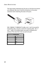
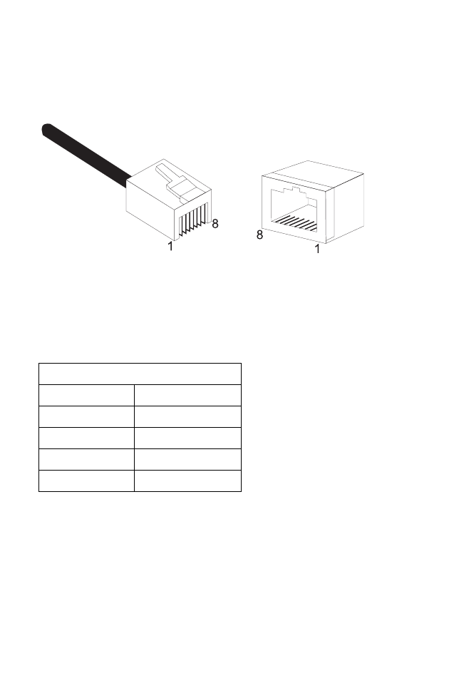
The figure below illustrates how the pins on the RJ-45 connector
are numbered. Be sure to hold the connectors in the same
orientation when attaching the wires to the pins.
With 10BASE-T/100BASE-TX cable, pins 1 and 2 are used for
transmitting data, and pins 3 and 6 for receiving data. The “+”
and “-” signs in the tables below are used to represent the
polarity of the wires that make up each wire pair.
RJ-45 Pin Assignments
Pin Assignment
1Tx+
2Tx-
3Rx+
6Rx-