3
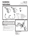
Light Kit Installation Instructions
A
E
B
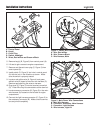
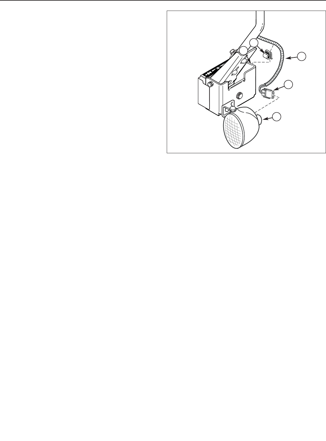
Figure 6. Light Connection
A. Light
B. Harness Plug
C. Headlight Wire Harness, w/Ribbed Plastic Cover
D. Wire Clip
E. Bracket
Note: The side of the headlight wire harness with the
ribbed plastic cover (C, Figure 6) connects to the left side
light. The side of the headlight wire harness with the
braided cover goes to the right side light.
13. Connect harness plug (B, Figure 6) to the back of the
headlight (A). Make sure the connector is fully seat-
ed into the light.
14. Slide wire clip (D) onto the back side of bracket (E)
as shown. Push down to secure.
15. Slide headlight wire harness (C) into wire clip (D).
Pull slack out of headlight wire harness (C) toward
engine compartment. Route wires so they do not
contact hot or moving components.
16. Repeat step 13, 14 & 15 on the other side of unit.
17. Lower seat to normal operating position.
18. Operate control levers to be sure wires, clips and
lights do not make contact with levers. If so, readjust
components so there is no interference.
19. Reconnect spark plug.
OPERATION
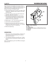
1. Start the unit using normal procedures. After the unit
has warmed up and is operating at full throttle the
lights may be turned on.
2. Turn the lights off before turning off the unit. If lights
are left on with out running the unit they will drain the
battery.
Note: The headlights may dim if the RPM’s of the engine
become to low.
D
C


