5-35
ROUTING SWITCHER SYSTEM (E)
5-2. Setting Items of the Secondary Station
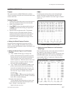
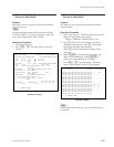
Example of setting :
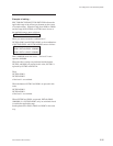
SRC TOP-SRC END=DST TOP-DST END indicates the
applicable range of the offset-type phantom on the screen
of example setting. When the range from IN001 to IN008,
and the range from OUT001 to OUT004 are to be set as
the applicable range, enter as follows.
IN001-IN008=OUT001-OUT004
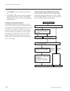
When you want execute the combinations of
OUT001<IN001 and OUT002<IN002, or the combinations
of OUT003<IN001 and OUT004<IN002, enter as follows.
Phantom:
IN001: DST+0<IN001-10000000
IN001: DST+1<IN002-10000000
Here, 10000000 means the level-1. The level-2 corre-
sponds to 0100000.
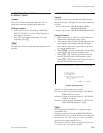
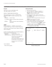
When the above settings are performed and the buttons
OUT001 and IN001 are pressed in this order, OUT001 is
replaced by OUT002 with DST+1.
Then,
OUT001<IN001
OUT002<IN002
of the level-1 are switched.
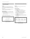
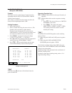
When the buttons OUT003 and IN001 are pressed in this
order,
OUT003<IN001
OUT004<IN001
of the level-1 are switched.
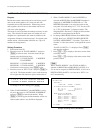
When OUT005 and IN001 are pressed, DST+0<IN001-
10000000 (i.e., OUT005<IN001) only are switched since it
is outside the applicable range.
Set the phantom for IN003, IN005 and IN007 in the same
way.


