9
Part Location and Function
Chapter 1 Introduction
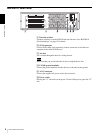
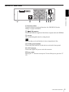
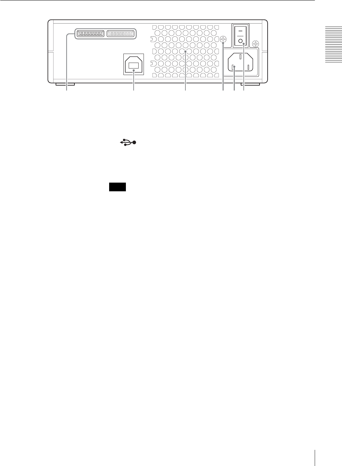
BW-RU101 Rear Panel
A Function switches
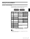
Use these switches to set the unit functions. See “BW-RU101 Function
Settings” on page 18 for details
B USB connector
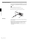
Connect the USB cable supplied to link the host computer and/or the USB Hub.
C Air duct
Air is sucked through the duct for cooling the unit.
Note
Make sure that you do not block the air duct or impede the air flow.
D F.GND (ground terminal)
Connect the ground terminals of other devices to the unit's frame ground.
E AC IN connector
Connect the supplied AC power cord to this connector.
F Power switch
Pressing the “ ? ” side turns on the power. To turn off the power, press the “a”
side.
234561


