AAAAyA<H.L0.idx>
6
Location and Function of Parts
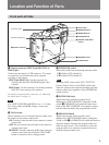
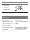
6 RETURN 1/RETURN 2 buttons
Select the return video signal
1)
to be output from the
RETURN OUT connector and to the camera’s
viewfinder.
Press the RETURN 1 or RETURN 2 button to select
the return video signal 1 or return video signal 2 from
the camera control unit.
To show the shooting picture on the viewfinder screen,
release the button. The return video signal which
selected last is still output from the RETURN OUT
connector if the button is released.
7 BREAKER button
The power to this unit is cut off when the circuit
breaker is activated by a power source or connection
problem. After resolving the problem, press this button
to reset the breaker.
If the breaker gets activated even after correcting the
connection, contact your Sony dealer.
8 POWER switch
Turns this unit’s power supply on and off.
To power the unit, set the switch to EXT or CCU
according to the type of power source being used.
Set this to OFF to turn off the power supply.
When this unit is connected to a camera control unit
via a triaxial cable, the following functions continue to
operate even after the power is turned off.
• Intercom communication
• On/off control of the back tally indicator (when
TALLY switch is ON)
• Calling via CALL button
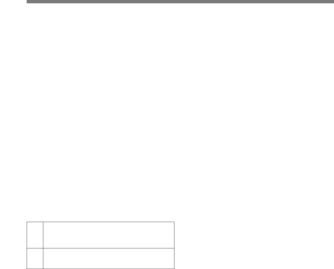
EXT Power supplied via an optional CMA-8A/8ACE AC
Adaptor connected to the DC IN connector (when
this unit is connected to a camera control unit via a
coaxial cable)
CCU Power supplied via camera control unit (when this
unit is connected to a camera control unit via a
triaxial cable)
1) Return video: Video signals that are sent from a camera
to a camera control unit and returned to the same or
another camera so that the camera operators can check
the recorded image.
..........................................................................................................................................................................................................


