5-56
ROUTING SWITCHER SYSTEM (E)
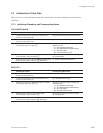
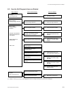
5-7. Initialization of Table Data
HDS-V3232 :
Initializing Procedure Corresponding Menu Items
1 1. Set the test switch (S2) on the CPU-251 board to “D”. All items of the primary and secondary stations.
2. Press the reset switch (S8).
2 1. Set the test switch (S2) on the CPU-251 board to “C”. [W : SYSTEM STATUS LOG]
2. Press the reset switch (S8).
3 Select the menu item [K : RESET TO DEFAULT TABLE] All items of the primary station excluding the
of the primary station and press [Y]. following 4 items.
. [H : SET GLOBAL PHANTOM]
. [N : SET DESCRIPTION NAME GROUP]
. [O : SET TIE LINES]
. [W: SYSTEM STATUS LOG]
4 Select the menu item [K : reset To default table] All items of the secondary station excluding
of the secondary station and press [Y]. the crosspoint data.
5 Select the menu item [U : SELECT REMOTE PROTOCOL] [U : SELECT REMOTE PROTOCOL]
of the secondary station and press [F2] (DEFAULT).
n
The primary station of HDS-V3232 does not have the menu item[S].
The secondary station of the menu item [Z] of [SWITCHING FIELD] only.
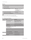
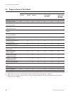
5-7-2. Default Values Initialization
Item Default Value
Primary station [B : SET SOURCE/DEST TYPE] TYPE : 0=IN, 1=OUT, 2-F=None
NAME : IN001-IN512, OUT001-OUT512
[E : SET LEVEL TABLE] All levels of all destination is ENABLE
Level name : 1, 2, 3....7, 8
[F : SET ACTIVE UNIT NUMBER] DVS-V3232B : STATION 2-33 ENABLE
DVS-V6464B : STATION 2-65 ENABLE
[H : SET GLOBAL PHANTOM] Not set
[J : NAME STYLE] Type + Num (“Type + Number” name mode)
[L : SET PHYSICAL ASSIGNMENT] Physical location number=Virtual location number
[M : SET INHIBIT TABLE] Not set
[N : SET DESCRIPTION NAME GROUP]
[O : SET TIE LINES]
[P : CHANGE PASSWORD]
[S : SELECT INDICATION COLOR] OFF
[U : SELECT CONTROL MODE] All channels : DIRECT
[V : SELECT WARNING DISPLAY] OFF
[W : SYSTEM STATUS LOG] NO LOG
[Z : SET UNIT DETECTABLE] All STATION : OFF
Secondary station [A : SET UNIT LOCATION ] No OFFSET
[U : SELECT REMOTE PROTOCOL] The input /output number is 1:1.
[Z : SELECT SDI FORMAT] 4:2:2, SWITCHING FIELD=FIELD
Crosspoint data The input/output number is 1:1.


