6-1
ROUTING SWITCHER SYSTEM (E)
Section 6
Confirmation of function
6-1. Outline
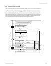
After the hardware and software have been set up, it is necessary to check if the system is working
properly before starting the operation.
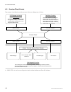
Each routing switcher is equipped with the self-diagnosis function to check the system connection and
status of each unit. As soon as the power of the unit is supplied or the system is reset, this function begins
operations which check internal conditions and connections automatically. When a fault is detected, this
is immediately displayed via the following four methods.
1. Status indicator
2. System status screen (*)
3. Error No. indicator
4. LEDs on the boards
Moreover, the test mode and ISR function are available to find out the detail of error and cause.
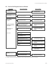
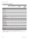
This section outlines the checks performed when the system is started up, and describes error messages
displayed on [2. System status screen] in detail.
For details of [1. Status indicator], [3. Error No. indicator] and ISR function, refer to the operation manual
or maintenance manual provided with the unit. For [4. LEDs on the boards] and [Test mode], refer to the
maintenance manual.
* : The error messages displayed in [2. System Status Screen] are valid only when the control terminal is connected to the primary
station in the S-BUS control system.


