5-27
ROUTING SWITCHER SYSTEM (E)
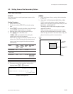
5-2. Setting Items of the Secondary Station
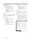
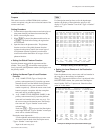
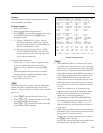
SONY ROUTING SYSTEM SETUP MENU BKS-R3204 V3.10 STATION NUMBER 16
SET PHANTOM TABLE (PHANTOM:DESTINATION<SOURCE-LEVEL) (G.PHANTOM NAME:NUMBER)
IN001 :OUT001 <IN001 -0 IN002 :OUT001 <IN002 -0 IN003 :OUT001 <IN003 -0
IN004 :OUT001 <IN004 -0 IN005 :OUT001 <IN005 -0 IN006 :OUT001 <IN006 -0
SONY007:OUT001 <SONY007-0 SONY008:OUT001 <SONY008-0 IN007 :OUT002 <IN001 -0
IN008 :OUT002 <SONY020-0 IN009 :OUT002 <IN003 -0 IN010 :OUT002 <IN004 -0
VTR005 :OUT002 <IN005 -0 VTR006 :OUT002 <IN006 -0 VTR007 :OUT002 <IN007 -0
VTR008 :OUT002 <IN008 -0 SONY009:OUT001 <SONY009-0 SONY010:OUT001 <SONY010-0
IN011 :OUT001 <IN011 -0 IN012 :OUT001 <IN012 -0 SONY013:OUT001 <SONY013-0
SONY014:OUT001 <SONY014-0 SONY015:OUT001 <SONY015-0 IN016 :OUT001 <IN016 -0
VTR009 :OUT002 <IN009 -0 VTR010 :OUT002 <IN010 -0 VTR011 :OUT002 <IN011 -0
VTR012 :OUT002 <IN012 -0 VTR013 :OUT002 <IN013 -0 VTR014 :OUT002 <IN014 -0
VTR015 :OUT002 <IN015 -0 VTR016 :OUT002 <SONY020-0 .......:.......<.......-.
.......:.......<.......-. .......:.......<.......-. .......:.......<.......-.
.......:.......<.......-. .......:.......<.......-. .......:.......<.......-.
.......:.......<.......-. .......:.......<.......-. .......:.......<.......-.
.......:.......<.......-. .......:.......<.......-. .......:.......<.......-.
.......:.......<.......-. .......:.......<.......-. .......:.......<.......-.
.......:.......<.......-. .......:.......<.......-. .......:.......<.......-.
.......:.......<.......-. .......:.......<.......-. .......:.......<.......-.
.......:.......<.......-. .......:.......<.......-. .......:.......<.......-.
0
=SONY 1=VTR 2=SUP 3=CB 4=AIR 5=ME 6=PGM 7=CL
8=SL 9=L A=RET B=MIX C=JEEP D=OSC E=L/A F=REN
Ctrl-E:MENU Ctrl-D:RETURN Ctrl-N:NAME G:GLOBAL PHANTOM
H: SET PHANTOM TABLE
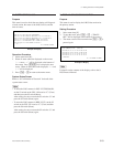
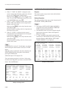
Purpose
This menu is used to set PHANTOM which switchers
several crosspoints, using the source selection button of the
remote control unit.
Setting Procedure
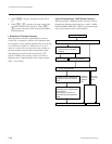
1. Call the menu screen of the remote control unit to be set,
using menu item [R], and then select menu item [H].
2. Select a item using the cursor.
3. When [Enter] is pressed, the phantom table can be set.
If [Enter] is pressed before setting, the registration
will be deleted.
4. Input the data to the phantom table. The phantom
function consists of the global phantom function
registered at the primary station, the normal type of
local phantom function registered at each remote
control unit and the destination off set type of local
phantom function.
..
..
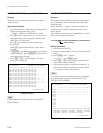
. Setting the Global Phantom Function
Input the phantom name with the type name and the
number. Next, press [G] at destination name position.
Lastly, input the global phantom number (four digits) set at
the primary station.
..
..
. Setting the Normal Type of Local Phantom
Function
a) At [J : NAME STYLE (Type + Num)] in the
primary station menu item [J], input the type name
(between 0 and F) and the number for the phantom
name, destination name, source name and level
number respectively. (When the remote control unit
button is pressed, crosspoints with the same phan-
tom name will be switched together.)
b) At [J : NAME STYLE (DESCRIP. NAME)] in the
primary station menu item [J], input the phantom
name and level number in the same way as a). For
the source name and destination name, the Descrip-
tion name and “Type + Number” name can be
selected freely.
Each time [Ctrl] _ [N] are pressed, the Description
name input mode and “Type + Number” name input
mode will be switched alternately.
Description name input mode :
Use the alphabet and numerical keys to enter seven
characters from the head of the Description name.
“Type + Number” name input mode :
Input in the same way as a).
n
If a Description name has been set for the input/output
number, the display of Description has priority to the
display of “Type + Number” even if the “Type + Number”
name is set.
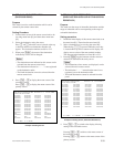
Example of Setting Screen (Normal Type)
..
..
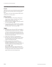
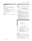
. Setting the Local Phantom of the Destination
Offset Type
Enter the phantom name, source name and level number in
the same way as the ordinary local phantom.
When [+] is depressed while the cursor is positioned in the
DESTINATION column, the system enters the Replace-
ment Variable “DST + n” input mode. Enter the offset
value “n” in this status.
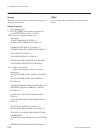
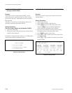
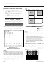
Example of Setting Screen (Destination Offset Type)
SONY ROUTING SYSTEM SETUP MENU BKS-R3216 V1.00 STATION NUMBER 4
SET PHANTOM TABLE (PHANTOM:DESTINATION<SOURCE-LEVEL) (G.PHANTOM NAME:NUMBER)
PHANTOM | DEST | SOURCE | LEVEL1-8 | PHANTOM | DEST | SOURCE | LEVEL1-8
SONY001 : OUT001 < IN001 - 10000000 | ....... : ....... < ....... - 00000000
....... : ....... < ....... - 00000000 | ....... : ....... < ....... - 00000000
....... : ....... < ....... - 00000000 | ....... : ....... < ....... - 00000000
....... : ....... < ....... - 00000000 | ....... : ....... < ....... - 00000000
....... : ....... < ....... - 00000000 | ....... : ....... < ....... - 00000000
....... : ....... < ....... - 00000000 | ....... : ....... < ....... - 00000000
....... : ....... < ....... - 00000000 | ....... : ....... < ....... - 00000000
....... : ....... < ....... - 00000000 | ....... : ....... < ....... - 00000000
....... : ....... < ....... - 00000000 | ....... : ....... < ....... - 00000000
....... : ....... < ....... - 00000000 | ....... : ....... < ....... - 00000000
....... : ....... < ....... - 00000000 | ....... : ....... < ....... - 00000000
....... : ....... < ....... - 00000000 | ....... : ....... < ....... - 00000000
....... : ....... < ....... - 00000000 | ....... : ....... < ....... - 00000000
....... : ....... < ....... - 00000000 | ....... : ....... < ....... - 00000000
....... : ....... < ....... - 00000000 | ....... : ....... < ....... - 00000000
....... : ....... < ....... - 00000000 | ....... : ....... < ....... - 00000000
0=IN 1=OUT 2=SONY 3=VTR 4=SUP 5=CB 6=AIR 7=ME
8=PGM 9=CL A=SL B=L C=RET D=MIX E=JEEP F=OSC
G=L/A H=REM I=CAM J=STDO K=AUX L=COV M=BS N=CS
O=SAT P=CG Q=WETH R=TEST S=HD T=D1- U=D2- V=SEG
Ctrl-E:MENU Ctrl-D:RETURN Ctrl-N:Type + Num G:GLOBAL PHANTOM +:DST+


