


– 25 –
KP-43T75A/53SV75A
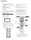
RM-Y906RM-Y906
SECTION 2
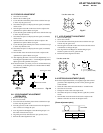
DISASSEMBLY
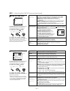
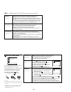
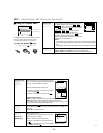
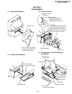
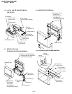
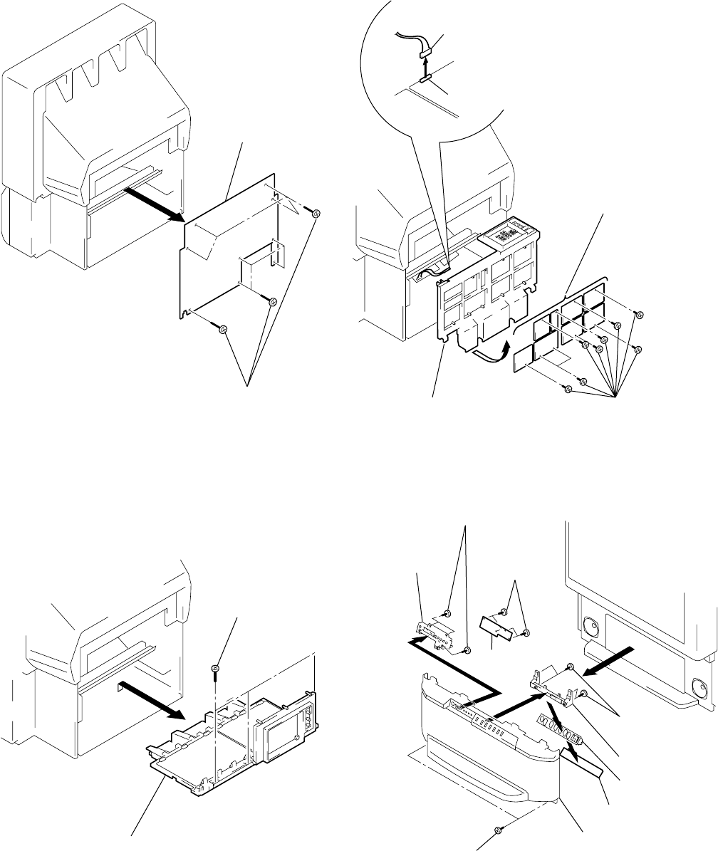
2-1. REAR BOARD REMOVAL 2-3. SERVICE POSITION
2-2. CHASSIS ASSY REMOVAL
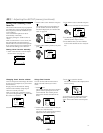
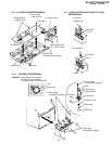
2-4. HA BOARD AND HB BOARD REMOVAL
(KP-53SV75A)
2 Rear board
1 Nine screws (KP-53SV75A)
Eight screws (KP-43T75A)
(Screw(4x20), tapping)
1 Three screws
(Screw(4x20),tapping)
2 Chassis assy
1 Disconnect CN203
on A board.
From CG board CN1304.
(The extension cable is not
supplied because of the
countermeasure for radiation.)
G board
CN203
A board
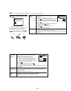
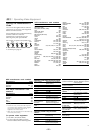
2 Covers
Cut them off with a plier or the like
from chassis assembly in case of
checking printed circuit boards.
After checking, turn over the covers
and secure them with screws.
Screws
(+BVTP3x12)
Chassis assembly
8 Three screws
(+BVTP 3x12)
6 Four screws
(+BVTP 4x12)
2 Two screws
(+BVTP 4x12)
1 Two screws
(Screws (4x20), tapping)
9 HB board
7 HB bracket
Speaker grille assy
5 HA board
3 HA bracket
4 Multi button