


– 27 –
KP-43T75A/53SV75A
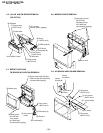
RM-Y906RM-Y906
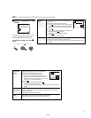
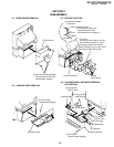
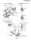
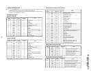
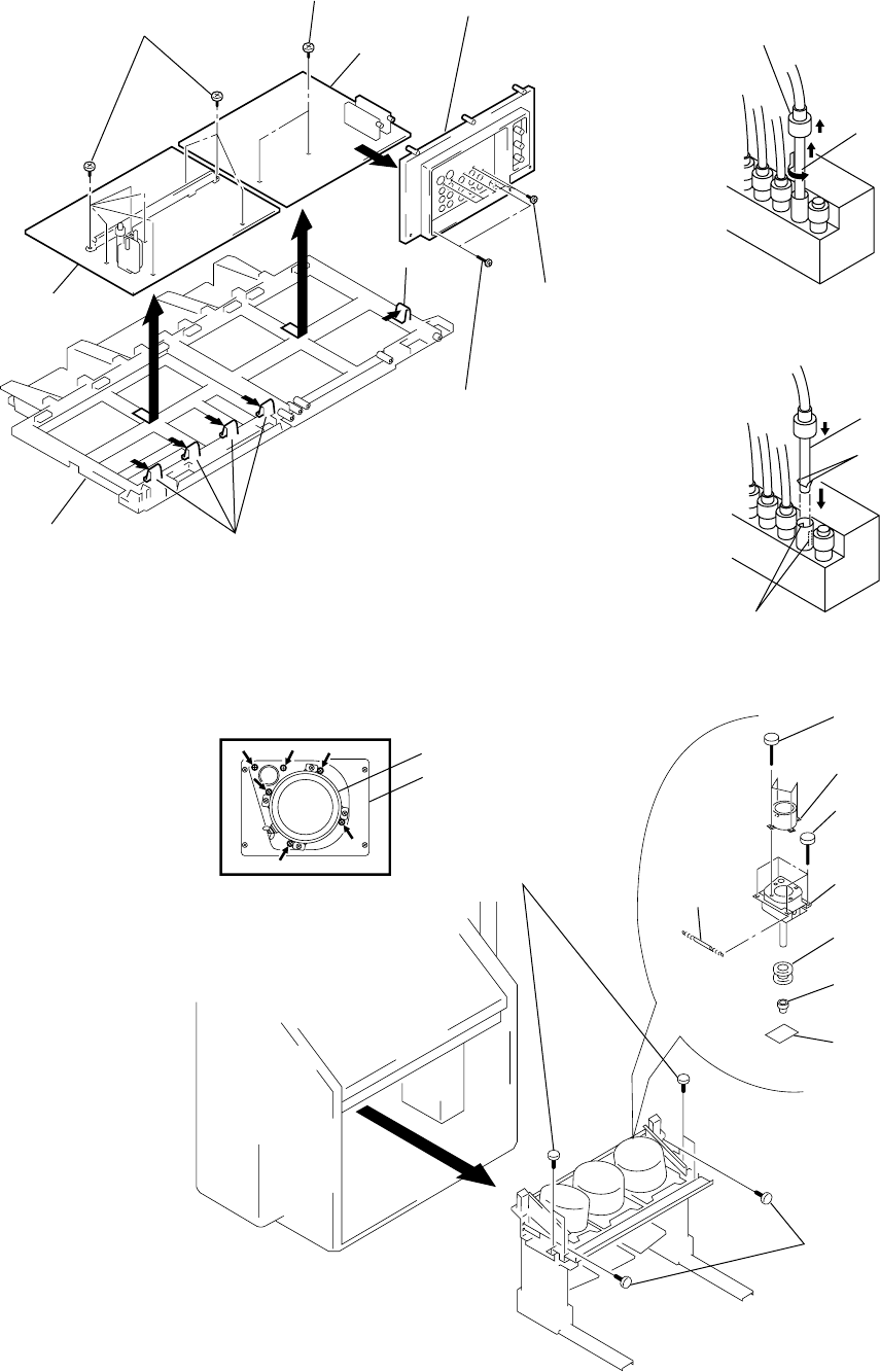
2-9. A, G AND FA BOARDS REMOVAL 2-11. HIGH-VOLTAGE CABLE INSTALLATION
AND REMOVAL
7 Two screws
(+BVTP 3x12)
4 Eight screws
(+BVTP 3x12)
6 G board
9 A board
3 Terminal board
8 Claw
5 Claws
Main bracket
1 Two screws
(Screws (4x20), tapping)
2 Seven screws
(+BVTP 3x12)
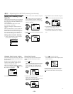
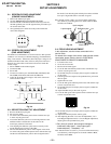
2-10. PICTURE TUBE REMOVAL
4 Four screws
(Screw(4x20), tapping)
!º Four screws
(+BVTP 4x12)
!¡ Picture tube
Picture tube
8 Diflection yoke
9 Tension
spring
2 Four screws
(Screw(4x20), tapping)
3
1 Four screws
(Screw(4x20), tapping)
7 Neck assy
6 CR board
5 Lens
Lens
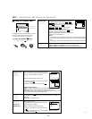
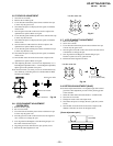
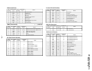
CAUTION: Removing the arrow-marked
screws is strictly prohibited.
If removed, it may cause liquid spill.
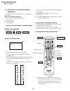
(1) Removal
1 Rubber cap
2 HV cable
turn 90°
1 HV cable
Gutter
Hook
(2) Installation