


– 39 –
KP-43T75C/53SV75C/61SV75C
RM-Y906RM-Y906RM-Y906
SECTION 4
SAFETY RELATED ADJUSTMENTS
4-1. HV REGULATION CIRCUIT CHECK AND
ADJUSTMENT
When replacing the following components marked with
on the schematic diagram always check HV regulation, and
if necessary re-adjust.
: C517
: C517, C521, C522
IC654, L504
T502, T504 (FBT)
D.Y, A board, G board
OPERATION CHECK
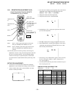
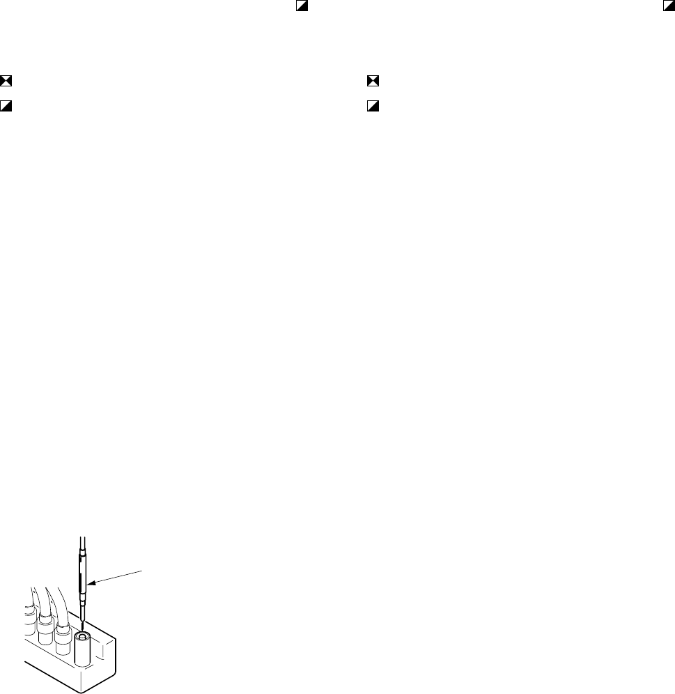
1. Connect a HV static voltmeter to the unconnected plug of
the high-voltage block. (Fig.4-1)
2. Power on the set.
3. Receive the dot signal. (PICTURE and BRIGHTNESS to
minimum)
4. Check that the HV static voltmeter is
reading 31.00
+0.95
kVdc.
-1.45
HV Regulation adjustment
1. Connect a HV static voltmeter to the unconnected plug of
the hight-voltage block.
2. Power on the set.
3. Receive the dot signal. (PICTURE and BRIGHTNESS to
minimum)
4. If anode voltage is 31.95kV or higher, replace C517 of 470PF/
2kV with that of 680PF/2kV, and check if the voltage is within
the standard range.
5. If anode voltage is 29.66kV or lower, replace C517 of 470PF/
2kV with that of 100PF/2kV, and check if the voltage is within
the standard range.
4-2. HV HOLD DOWN CIRCUIT OPERATION
CHECK AND ADJUSTMENT
When replacing the following components marked with
on the schematic diagram always check hold-down voltage
and if necessary re-adjust.
: R536, R545
: C516, C536
D506, D507, D522
IC206, IC502, IC654
L504, R511, R522, R536, R538, R545,
R548, R584
T502, T504 (FBT)
D.Y, A board, G board
OPERATION CHECK
1. Remove CN652 connecter.
2. Short-circuit across TP-PROT and ground.
3. Connect a HV static voltmeter to the unconnected plug of
the high-voltage block.
4. Connect a 220 Ω/200W variable resistor, across pin 2 and
pin 1 of CN652 and connect an external dc power supply
unit (200V, class 2A) to pin 3 of CN652.
5. First turn on the external power supply (+B=135V), then turn
on the power of the set.
6. Receive the dot signal. (PICTURE and BRIGHTNESS to
minimum)
7. Gradually increase the value of the external dc power supply
and check that the hold-down circuit operates at a static volt-
meter reading of 33.5±0.95kVdc when the raster disappears.
HV HOLD-DOWN ADJUSTMENT
1. Repeat steps 1 ~ 7 as above.
2. If hold down voltage is 34.45kV or higher, remove R536,
mount a resistor (150kΩ, 1/4W : RN) onto R545 instead, and
check again if the hold-down voltage is within the standard
range.
3. If hold down voltage is 32.55kV or lower, mount a resistor
(220kΩ, 1/4W : RN) onto R536 and check again if the hold-
down voltage is within the standard range.
NOTE : Please finish the adjustment as soon as possible
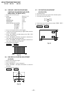
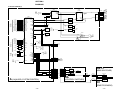
[ G BOARD]
Remove the cap off from
the unused terminal and
cpmmect a static voltmeter
there.
Fig. 4-1