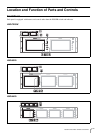
Location and Function of Parts and Controls
9
GB
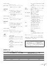
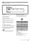
Rear
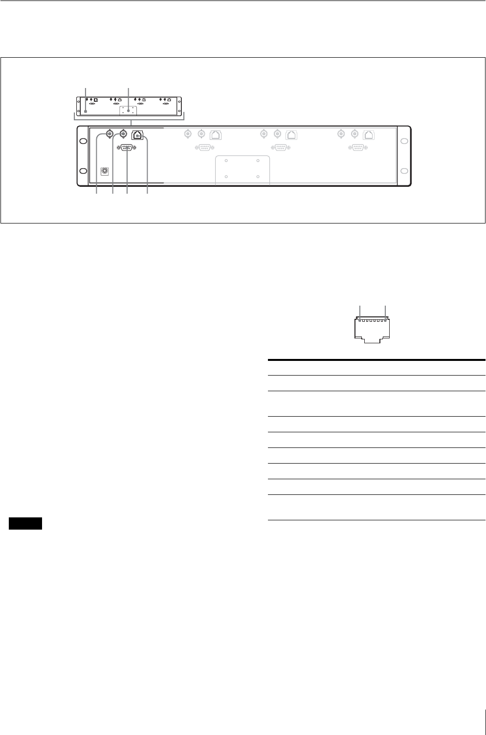
The illustration refers to LMD-4420.
Each panel is equipped with connectors other than the DC IN jack and AC adaptor attachment.
A DC IN jack
Connect the supplied AC adaptor.
B AC adaptor attachment
Attach the supplied AC adaptor.
C VIDEO IN connector (BNC)
Connect to the video output connector of the VCR,
etc.
When input adaptor BKM-320D is connected to the
OPTION IN connector, this connector does not
function.
An optional input (OPTION) and video input
(VIDEO) can be switched by using the REMOTE
connector.
D VIDEO OUT connector (BNC)
Loop-through output of the VIDEO IN connector.
The connector is automatically terminated at 75 ohms.
E OPTION IN connector (D-sub 9 pin, female)
When optional Sony input adaptor BKM-320D is
connected, SDI signals are input.
NOTE
Do not install the other equipment than BKM-320D.
It causes to damage the unit or the equipment.
F REMOTE connector (modular)
Forms a parallel switch and controls the monitor
externally. The pin assignment and factory setting
function assigned to each pin are given below.
*Functions when BKM-320D is connected. When
both pins are shorted, OPTION IN (SDI) is prior to
VIDEO IN.
**LMD-7220W only
LMD-5320/4420: N.C
To switch each function between high and low, change
pin connections in the following way.
High: Leave each pin open.
Low: Short each pin and 5-pin at the same time.
12
345 6
Pin number Function (High y Low)
1 VIDEO IN (OFF y ON)*
2 OPTION IN
(SDI)
(OFF y ON)*
3Tally Red(OFF y ON)
4 Tally Green (OFF y ON)
5 Ground
6N.C
7N.C
8 16:9/4:3
Selectable
(16:9 y 4:3)**
1 8


