


9 (EN)
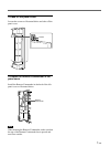
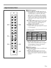
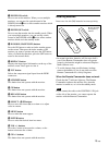
Right Connector Panel
1 RGB1 IN connectors
R (R-Y)/G (Y)/B (B-Y) IN (BNC-type): Input the
analog RGB signal or component signal. Connect
to the RGB signal or component (Y/B-Y/R-Y)
signal output of a computer or video equipment.
This unit also accepts the HD analog component
(Y/P
B/PR) signal. Input the PB signal to the B (B-
Y) IN connector and P
R signal to the R (R-Y) IN
connector.
HD/COMP IN (BNC-type): Input the H sync signal
or composite sync signal. Connect to the H sync
signal or composite sync signal output of a
computer or video equipment.
VD IN (BNC-type): Input the V sync signal.
Connect to the V sync signal output of a computer
or video equipment.
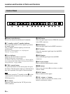
External sync signal is selected automatically. See the
priority chart below.
AUDIO IN (L/R) (phono type): Input the audio
signal. Connect to the audio output of a computer
or video equipment. Connect to the channel L
when the audio signal is monaural.
2 RGB2 IN connectors
RGB IN (D-sub 15-pin): Connect to the RGB signal
output of a computer.
AUDIO IN (L/R) (phono type): Input the audio
signal. Connect to the audio output of a computer.
Connect to the channel L when the audio signal is
monaural.
(Continued)
RGB IN
RGB 1
RGB 2
LINE
IN OUT
IN OUT
R
R-Y
G
Y
B
B-Y
HD/
COMP
VD
L
R
SYNC
AUDIO
Y/C
VIDEO
L
R
AUDIO
L
R
AUDIO IN
1
2
3
4
5
6
Input Input sync signals
connector
HD/COMP IN H Sync Comp Sync —
VD IN V Sync — —
G(Y) IN Sync on G Sync on G Sync on G
Sync signals H Sync Comp Sync Sync on G
to be selected V Sync