


7
GB
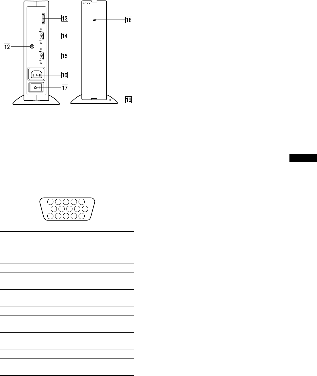
Media engine
qs
qsqs
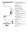
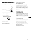
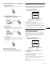
qs AUDIO IN jack (page 10)
This jack inputs audio signals when connecting to the audio
output jack of the computer or other audio equipment.
qd
qdqd
qd SYSTEM CONNECTOR (TO DISPLAY) (page 8)
This connector outputs signals to the display when the display
and the media engine are connected with a system connecting
cable.
qf
qfqf
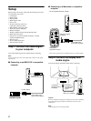
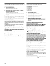
qf HD15 (RGB) input 1 connector (INPUT1) (page 8)
This connector inputs RGB video signals (0.700 Vp-p,
positive) and SYNC signals.
* DDC (Display Data Channel) is a standard of VESA.
qg
qgqg
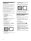
qg HD15 (RGB) input 2 connector (INPUT2) (page 8)
This connector inputs RGB video signals (0.700 Vp-p,
positive) and SYNC signals. The pin assignment is the same
as qf.
qh
qhqh
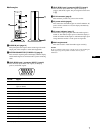
qh AC IN connector (page 9)
This connector provides AC power to the monitor.
qj
qjqj
qj AC power switch (page 9)
This switch turns the media engine on and off. When the AC
power switch is turned on or off, the display automatically
turns on or off.
qk
qkqk
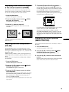
qk AC power indicator (page 17)
This indicator lights up in green when the media engine is
turned on. The indicator lights up in red when the display is
turned off with the media engine on. The indicator lights up in
orange when the monitor is in the power saving mode.
ql
qlql
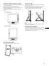
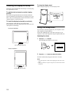
ql Media engine stand
This stand is used to install the media engine vertically.
Caution
Be sure to install the media engine vertically shown as left. Installing the
media engine lying flat may block ventilation, and may cause a
malfunction.
Pin No. Signal
1Red
2 Green
(Sync on Green)
3Blue
4 ID (Ground)
5 DDC Ground*
6 Red Ground
7 Green Ground
8 Blue Ground
9 DDC + 5V*
10 Ground
11 ID (Ground)
12 Bi-Directional Data (SDA)*
13 H. Sync
14 V. Sync
15 Data Clock (SCL)*
SYSTEM CONNECTER
(
TO DISPLAY
)
INPUT 1
INPUT 2
AUDIO IN
5 4 3 2
1
678910
1112131415