


11
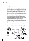
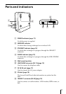
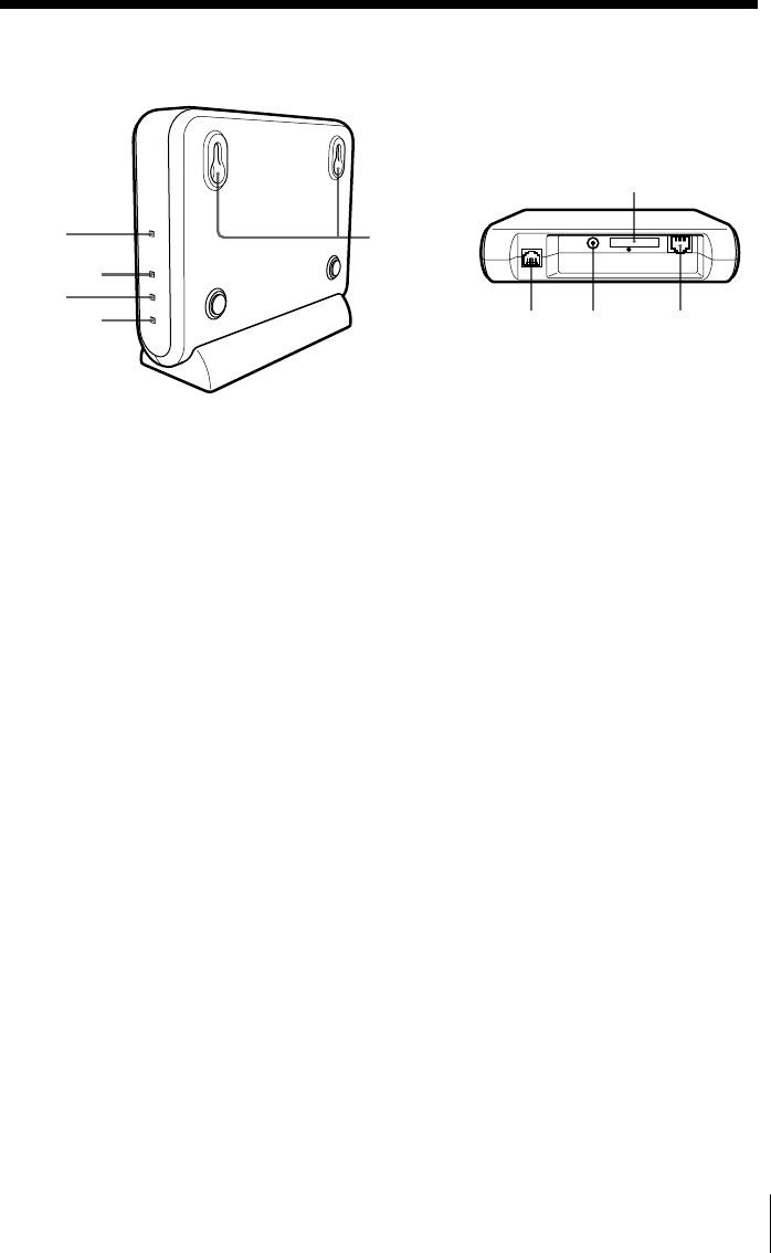
1 POWER indicator (page 17)
Lit while power is supplied.
2 WIRELESS indicator
Lit when data is being exchanged on a wireless LAN.
3 ETHERNET indicator (page 14)
Lit while data exchange is in progress through the 10BASE-T
connector.
4 PHONE indicator (page 12)
Lit while data exchange is in progress through the LINE/PHONE
connector.
5 Wall-mounting holes
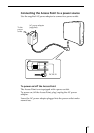
6 LINE/PHONE connector (RJ-11) (page 12)
Used to connect the telephone cable.
7 DC IN 9V jack (page 17)
Used to connect the AC power adapter.
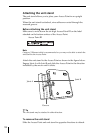
8 ID label (page 18)
The Access Point ID and other information are printed on this
label.
9 10BASE-T connector (RJ-45) (page 14)
Used to connect to a cable modem/ xDSL modem, ISDN router, or
hub.
Parts and indicators
8
LINE/
PHONE
DC IN 5V 10BASE-T
1
2
3
4
5
67 9