Appendix B :
Quick Installation Guide
This leaflet is meant to help you set the jumpers for your 5EAS motherboard in
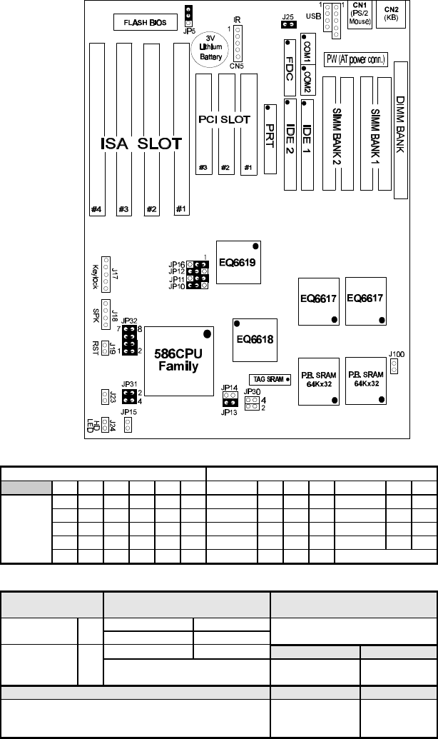
order to boot the motherboard. Please refer to Diagram 1 for the location of the
relevant jumpers:
Diagram 1: Board layout
Table 1 : Jumper settings for CPU voltage and frequency
Voltage Settings: JP32 (JP30, JP31) CPU frequency settings: JP10, 11, 12 / JP13, 14
voltage 1-2 3-4 5-6 7-8 JP30 JP31 frequency: JP10 JP11 JP12 multiplier JP13 JP14
single 3.52V
close close close close
open
close
50 Mhz 2-3 2-3 2-3 1.5 / 3.5x open open
single 3.3V
close close
open
close
open
close
55 Mhz 2-3 2-3 1-2 2.0x
close
open
dual 3.2V
close close
open open
close
open 60 Mhz 1-2 2-3 2-3 2.5x
close close
dual 2.9V
close
open open
close close
open 66 Mhz 2-3 1-2 2-3 3.0x open
close
dual 2.8V
close
open open open
close
open 75 Mhz 1-2 2-3 1-2
Table 2: Additional jumper settings
CMOS clear: J5 PCI bus synchronous / asynchronous:
J16
Sleep Switch connector: J23
PCI bus: JP16Retain CMOS
data (default)
1-2
synchronous 1-2
connect a switch to this jumper, Any
IRQ will wake up the system.
asynchronous 2-3
Reset: J19 HDD Led: J24
Clear CMOS data
2-3
note: Set JP16 to 2-3 when 75 Mhz bus
clock is selected, for 50 and 55 set 1-2.
Connect the reset
button to J19
connect the HDD
led to J24
J100: Cyrix CPU linear burst enable Speaker: J18 Powerled: J17
Close this jumper when using a Cyrix CPU. Set the ‘ linear burst’
item in the BIOS under ‘ chipset features’ to enabled as well when
setting this jumper. (default setting is disabled)
connect the speaker
to J18
connect keylock
& power led to
J17


