


Hardware Setup SY-5EHM/5EH5
23
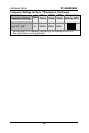
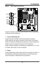
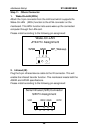
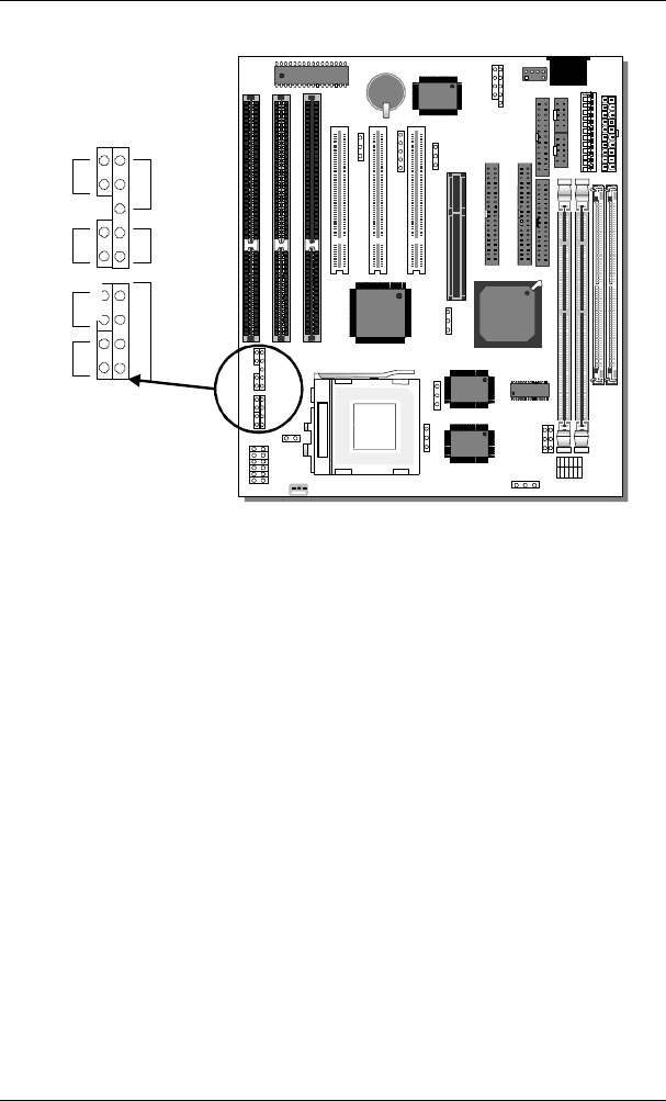
Step 9. Front Panel Connections
Plug the computer case's front panel devices to the corresponding
connectors on the mainboard.
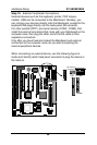
1. Power LED & KeyLock
Plug the Power LED cable into the 5-pin Keylock connector.
Some systems may feature a KeyLock function with a front panel
switch for enabling or disabling the keyboard. Connect the KeyLock
switch to the 5-pin Keylock connector on the mainboard.
Please install according to the following pin assignment: pin 1,3 are
for Power LED and pin 4,5 are for Keylock.
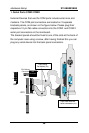
2. Reset
Plug the Reset push-button cable into the 2-pin Reset connector on
the mainboard. Pushing the Reset button on the front panel will
cause the system to restart the boot-up sequence.
6
5
4
3
2
1
*
RST
PW2
SPK
Keylock
Power
LED
Turbo
LED
HDD
LED
_
+