SY-P4I845PEISA/GEISA
Quick Start Guide
11
Hardware
Installation
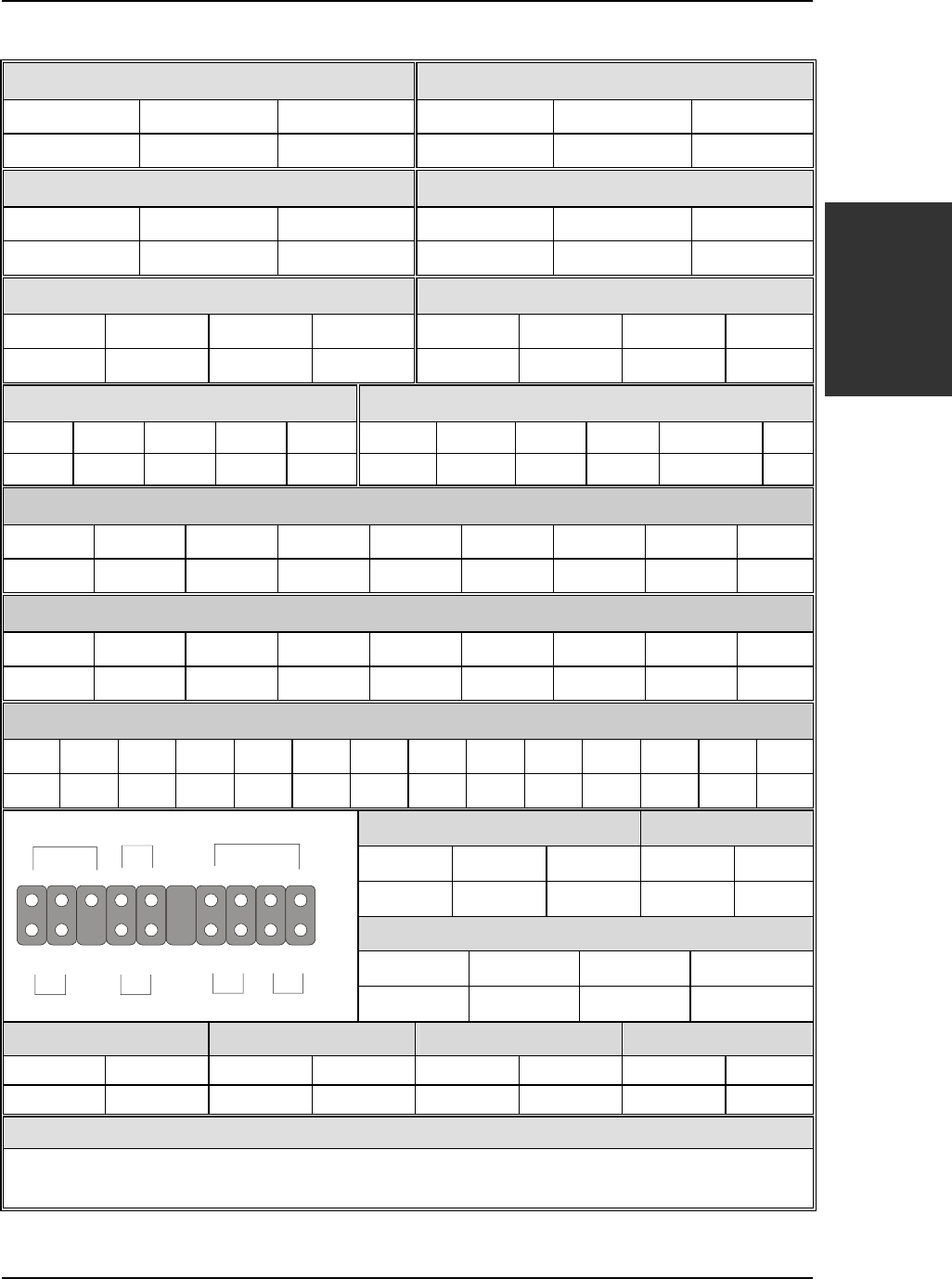
Connectors and Plug-ins
CPU Cooling Fan: CPUFAN1 CPU Cooling Fan: CPUFAN2
Pin1 Pin2 Pin3 Pin1 Pin2 Pin3
GND +12V Sensor GND +12V NC
Chassis Fan: CHAFAN1 Chassis Fan: CHAFAN2
Pin1 Pin2 Pin3 Pin1 Pin2 Pin3
GND +12V Sensor GND +12V Sensor
CD-IN 1 AUXIN1
Pin1 Pin2 Pin3 Pin4
Pin1 Pin2 Pin3 Pin4
Left GND GND Right Left GND GND Right
Standard IrDA (Infrared Device Header): SIRCON MIC & LED Connector: J30
Pin1 Pin2 Pin3 Pin4 Pin5 Pin1 Pin2 Pin3 Pin4 Pin5 Pin6
VCC NC IRRX GND IRTX
Line_Out_L Line_Out_R MIC IN GND
LAN_ACT_LED
VCC
USB20_1
Pin1 Pin2 Pin3
Pin4
Pin6 Pin7 Pin8
Pin9 Pin10
VCC DATA- DATA+
GND
VCC DATA- DATA+
GND GND
USB20_2
Pin1 Pin2 Pin3
Pin4
Pin6 Pin7 Pin8
Pin9 Pin10
VCC DATA- DATA+
GND
VCC DATA- DATA+
GND GND
SMCARDCN
Pin1 Pin2 Pin3 Pin4 Pin5 Pin6 Pin7 Pin8 Pin9 Pin10 Pin11 Pin12 Pin13 Pin14
VCC NC NC NC Scrfet RST CLK NC NC Scrio GND Scrpres NC NC
Power LED Key Lock
Pin11 Pin12 Pin13
Pin14 Pin15
VCC GND GND
Control Pin GND
Speaker
Pin17 Pin18 Pin19 Pin20
VCC NC NC Speaker out
HDD LED ACPI LED PWRBT RESET
Pin9 Pin10 Pin7 Pin8 Pin4 Pin5 Pin1 Pin2
LED Anode LED Cathode 2.5V_DDR Control Pin Power On/Off GND Control PIN GND
Power On/Off: PWRBT
Connect your power switch to this header (momentary switch type).
To turn off the system, press this switch and hold down for longer than 4 seconds.
Power LED
Key Lock
Speaker
Reset PWRBT
ACPI LED
HDD LED
++
+
+
_
_
_
_
11


