


USB Hub with Integrated 10/100 Ethernet Controller
Datasheet
SMSC LAN9512 11 Revision 1.0 (04-20-09)
DATASHEET
1
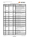
Ethernet Link
Activity Indicator
LED
nLNKA_LED OD12
(PU)
This pin is driven low (LED on) when a valid link is
detected. This pin is pulsed high (LED off) for
80mS whenever transmit or receive activity is
detected. This pin is then driven low again for a
minimum of 80mS, after which time it will repeat
the process if TX or RX activity is detected.
Effectively, LED2 is activated solid for a link. When
transmit or receive activity is sensed, LED2 will
function as an activity indicator.
General
Purpose I/O 1
GPIO1 IS/O12/
OD12
(PU)
This General Purpose I/O pin is fully programmable
as either a push-pull output, an open-drain output,
or a Schmitt-triggered input.
1
Ethernet Speed
Indicator LED
nSPD_LED OD12
(PU)
This pin is driven low (LED on) when the Ethernet
operating speed is 100Mbs, or during auto-
negotiation. This pin is driven high during 10Mbs
operation, or during line isolation.
General
Purpose I/O 2
GPIO2 IS/O12/
OD12
(PU)
This General Purpose I/O pin is fully programmable
as either a push-pull output, an open-drain output,
or a Schmitt-triggered input.
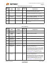
1
General
Purpose I/O 3
GPIO3 IS/O8/
OD8
(PU)
This General Purpose I/O pin is fully programmable
as either a push-pull output, an open-drain output,
or a Schmitt-triggered input.
1
General
Purpose I/O 4
GPIO4 IS/O8/
OD8
(PU)
This General Purpose I/O pin is fully programmable
as either a push-pull output, an open-drain output,
or a Schmitt-triggered input.
1
General
Purpose I/O 5
GPIO5 IS/O8/
OD8
(PU)
This General Purpose I/O pin is fully programmable
as either a push-pull output, an open-drain output,
or a Schmitt-triggered input.
1
General
Purpose I/O 6
GPIO6 IS/O8/
OD8
(PU)
This General Purpose I/O pin is fully programmable
as either a push-pull output, an open-drain output,
or a Schmitt-triggered input.
1
General
Purpose I/O 7
GPIO7 IS/O8/
OD8
(PU)
This General Purpose I/O pin is fully programmable
as either a push-pull output, an open-drain output,
or a Schmitt-triggered input.
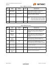
1
Detect
Upstream
VBUS Power
VBUS_DET IS_5V This pin detects the state of the upstream bus
power. The Hub monitors VBUS_DET to determine
when to assert the USBDP0 pin's internal pull-up
resistor (signaling a connect event).
For bus powered hubs, this pin must be tied to
VDD33IO.
For self powered hubs, refer to the LAN9512
reference schematics.
1
Auto-MDIX
Enable
AUTOMDIX_EN IS Determines the default Auto-MDIX setting.
0 = Auto-MDIX is disabled.
1 = Auto-MDIX is enabled.
1
Test 1 TEST1 - Used for factory testing, this pin must always be left
unconnected.
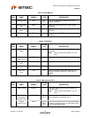
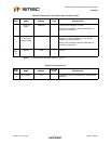
Table 2.3 Miscellaneous Pins (continued)
NUM
PINS NAME SYMBOL
BUFFER
TYPE DESCRIPTION