USB Hub with Integrated 10/100 Ethernet Controller
Datasheet
SMSC LAN9512 41 Revision 1.0 (04-20-09)
DATASHEET
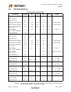
Note 4.6 This is the total 5.5V input leakage for the entire device.
Note 4.7 XI can optionally be driven from a 25MHz single-ended clock oscillator.
Note 4.8 Measured at line side of transformer, line replaced by 100Ω (+/- 1%) resistor.
Note 4.9 Offset from 16nS pulse width at 50% of pulse peak.
Note 4.10 Measured differentially.
Note 4.11 Min/max voltages guaranteed as measured with 100Ω resistive load.
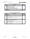
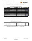
Table 4.3 100BASE-TX Transceiver Characteristics
PARAMETER SYMBOL MIN TYP MAX UNITS NOTES
Peak Differential Output Voltage High V
PPH
950 - 1050 mVpk Note 4.8
Peak Differential Output Voltage Low V
PPL
-950 - -1050 mVpk Note 4.8
Signal Amplitude Symmetry V
SS
98 - 102 % Note 4.8
Signal Rise and Fall Time T
RF
3.0 - 5.0 nS Note 4.8
Rise and Fall Symmetry T
RFS
--0.5nSNote 4.8
Duty Cycle Distortion D
CD
35 50 65 % Note 4.9
Overshoot and Undershoot V
OS
--5%
Jitter 1.4 nS Note 4.10
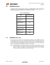
Table 4.4 10BASE-T Transceiver Characteristics
PARAMETER SYMBOL MIN TYP MAX UNITS NOTES
Transmitter Peak Differential Output Voltage V
OUT
2.2 2.5 2.8 V Note 4.11
Receiver Differential Squelch Threshold V
DS
300 420 585 mV


