


SMSC LPC47M997 Page 5 Rev. 01-12-07
PRODUCT PREVIEW
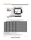
Package Outline
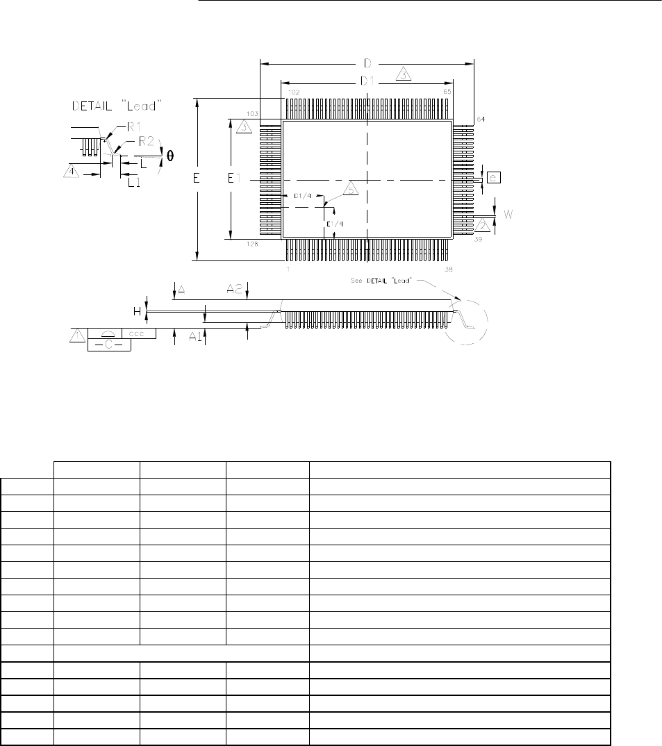
Figure 2 - 128 PIN QFP Package Outline, 14x20x2.7 Body, 3.2 mm Footprint
Table 1 - 128 PIN QFP Package Parameters
MIN NOMINAL MAX REMARKS
A
~ ~ 3.4 Overall Package Height
A1
0.05 ~ 0.5 Standoff
A2
2.55 ~ 3.05 Bod
y
Thickness
D
23.00 23.20 23.40 X Span
D1
19.90 20.00 20.10 X bod
y
Size
E
17.00 17.20 17.40 Y Span
E1
13.90 14.00 14.10 Y bod
y
Size
H
0.09 ~ 0.20 Lead Frame Thickness
L
0.73 0.88 1.03 Lead Foot Len
g
th
L1
~ 1.60 ~ Lead Len
g
th
e
0.50 Basic Lead Pitch
θ
0
o
~ 7
o
Lead Foot Angle
W
0.10 ~ 0.30 Lead Width
R1
0.08 ~ ~ Lead Shoulder Radius
R2
0.08 ~ 0.30 Lead Foot Radius
ccc
~ ~ 0.08 Coplanarit
y
Notes:
1. Controlling Unit: millimeter.
2. Tolerance on the position of the leads is ± 0.04 mm maximum.
3. Package body dimensions D1 and E1 do not include the mold protrusion.
Maximum mold protrusion is 0.25 mm.
4. Dimension for foot length L measured at the gauge plane 0.25 mm above the seating plane.
5. Details of pin 1 identifier are optional but must be located within the zone indicated.