


ARCNET 5 Port HUB Controller
Datasheet
Revision 1.1 (07-24-07) Page 10 SMSC TMC2005-JT
DATASHEET
OPERATIONAL DESCRIPTION
Direction Determination
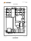
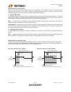
All TX ports are set to disable mode in the initial state. When a signal is received from any RX ports, the circuit holds
the port on receiving mode (disable TX) and changes the other ports to sending mode (disable RX). One port stays in
RX and the rest change into TX after all. The circuit initializes the internal DPLL on the timing of received RX pulse,
and the RX buffer circuit stores the RX data and filters its jitter. TX controlling circuit regenerates the stored RX pulse
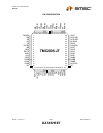
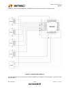
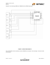
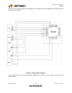
on nPULSE1, nPULSE2 and nP1BAK. The nPULSE1 and nPULSE2 are pulse output pins for transceivers
(HYC9088A) of ARCNET normal mode. The nP1BAK is a pulse output pin for transceiver (HYC5000/4000/2000 and
RS485 driver) of ARCNET back plane mode. When using optical transceiver, instead of these signals, TXENA [0:1],
TXENB [0:1], EXTTX (MA, MB, ME = 0) must be used as TX data inputs of the optical transceiver.
Direction Release
On ARCNET protocol, each TX message starts with 6-bits of “1” ALERT and each data byte is lead by three bits (1, 1,
0) preamble. To control the HUBs direction, the circuit monitors this bit pattern and holds the state. If the end of the bit
pattern comes, all TX ports return receiving mode (disable TX) again. The interval timer detects the end of the bit
pattern. During data is on line, silent period is less than 4 uS* because at least one bit “1” among 10-bits is received
while receiving the data. The minimum silent interval from the end of received data to the alert of the next data (the
minimum time of changing the direction) is the chip turn around time (12.6 uS*) of ARCNET controller. The interval
timer to detect the data end is set to 5.6uS by adding some margin to the above interval for neglecting the reflection
on a cable.
[Note] Numbers marked * are at 2.5Mbps operation.
Jitter Filter
To build a network with transceivers that introduce big jitter like ones for optical fiber, the old HUB that has direction
control only may cause a transmission error because jitters on each HUB are added when several HUBs were
connected in serial. The TMC2005 fixes that problem with jitter filtering and wave shaping through the following three
steps.
1) Input Sampling
The TMC2005 samples a data on a network by eight times clock of the network data.
2) Jitter Filtering (DPLL)
The TMC2005 filters the jitter (± 100nS at 2.5Mbps) of network data sampled by 8X clock through the internal digital
PLL and stores the data into the buffer.
3) Wave Shaping Output
The TMC2005 re-synchronizes and regenerates the network data at the same clock as the data rate.
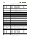
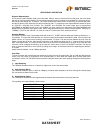
The capability of the jitter filtering is shown below.
DATA RATE CAPABILITY OF JITTER FILTERING
10Mbps ± 25nS
5Mbps ± 50nS
2.5Mbps ± 100nS
1.25Mbps ± 200nS
625Kbps ± 400nS
312.5Kbps ± 800nS
156.25Kbps ± 1.6uS