Ultra Fast USB 2.0 Multi-Slot Flash Media Controller
Datasheet
Revision 1.1 (05-29-08) 32 SMSC USB2250/50i/51/51i
DATASHEET
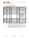
Note 7.9 The assignment of each Integrated Card Power FET to a designated Card Connector is
controlled by both firmware and the specific board implementation. Firmware will default to
the settings listed in Table 10.1, “USB2250/50i/51/51i GPIO Usage (ROM Rev 0x00),” on
page 35.
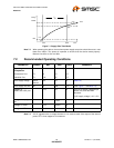
Note 7.10 The 3.3V supply should be at least at 75% of its operating condition before the 1.8V supply
is allowed to ramp up.
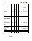
7.4 Capacitance
T
A
= 25°C; fc = 1MHz; V
DD,
V
DDP
= 1.8V
Table 7.1 Pin Capacitance
PARAMETER SYMBOL
LIMITS
UNIT TEST CONDITIONMIN TYP MAX
Clock Input Capacitance C
XTAL
2 pF All pins (except USB pins
and pins under test) are tied
to AC ground.
Input Capacitance C
IN
10 pF
Output Capacitance C
OUT
20 pF


