Integrated USB 2.0 Compatible 3-Port Hub
Datasheet
SMSC USB2503/USB2503A 11 Revision 2.3 (08-27-07)
DATASHEET
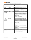
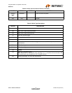
Port Power
Polarity strapping.
PRTPWR_POL I/O12 Port Power Polarity strapping determination for the active
signal polarity of the PRTPWR[3:1] pins.
While RESET_N is asserted, the logic state of this pin will
(though the use of internal combinatorial logic) determine
the active state of the PRTPWR[3:1] pins in order to ensure
that downstream port power is not inadvertently enabled to
inactive ports during a hardware reset.
When RESET_N is negated, the logic value will be latched
internally, and will retain the active signal polarity for
PRTPWR[3:1] pins.
‘1’ = PRTPWR[3:1] pins have an active ‘high’ polartity
‘0’ = PRTPWR[3:1] pins have an active ‘low’ polarity
Over Current
Sense
OCS[3:1]_N IPU Input from external current monitor indicating an over-
current condition. {Note: Contains internal pull-up to 3.3V
supply}
USB Transceiver
Bias
RBIAS I-R A 12.0kΩ (+/− 1%) resistor is attached from ground to this
pin to set the transceiver’s internal bias settings.
SERIAL PORT INTERFACE
Serial Data/SMB
Data
SDA/SMBDATA IOSD12 (Serial Data)/(SMB Data) signal.
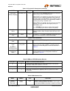
Serial Clock/SMB
Clock
&
Chip Select /
EEPROM Select
SCL/SMBCLK/
CFG_SEL0
IOSD12 (Serial Clock)/(SMB Clock) signal. This multifunction pin is
read on the rising edge of RESET_N negation and will
determine the hub configuration method as described in
Table 4.2.
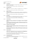
SMB
Programming
Select
CFG_SEL1 I This pin is read on the rising edge of RESET_N negation
and will detemine the hub configuration method as
described in Table 4.2.
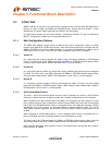
Table 4.2 SMBus or EEPROM Interface Behavior
CFG_SEL1 CFG_SEL0 SMBus or EEPROM interface behavior.
0 X Configured as an SMBus slave for external download of user-defined
descriptors. SMBus slave address is :0101101
1 0 Internal Default Configuration via strapping options.
1 1 2-wire (I2C) EEPROMS are supported, and CFG_SEL0 has no other
functionality.
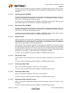
Table 4.3 Miscellaneous Pins
NAME SYMBOL TYPE FUNCTION
Crystal
Input/External
Clock Input
XTAL1/
CLKIN
ICLKx 24MHz crystal or external clock input.
This pin connects to either one terminal of the crystal or
to an external 24MHz clock when a crystal is not used.
Table 4.1 3-Port Hub Pin Descriptions (continued)
NAME SYMBOL TYPE FUNCTION


