


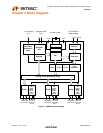
Industrial Temperature Rated USB 2.0 High-Speed 3-Port Hub Controller
Datasheet
Revision 1.98 (11-19-07) 12 SMSC USB2513i
DATASHEET
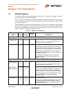
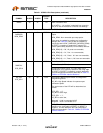
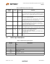
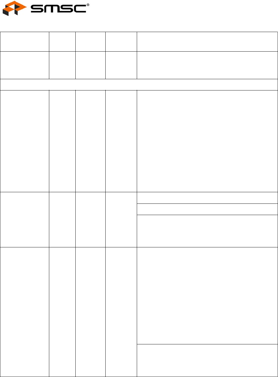
RBIAS 35 47 I-R USB Transceiver Bias
A 12.0kΩ (+/- 1%) resistor is attached from ground to
this pin to set the transceiver’s internal bias settings.
SERIAL PORT INTERFACE
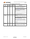
SDA/
SMBDATA/
NON_REM1
22 29 I/OSD12 Serial Data / SMB Data & Port Non Removable Strap
Option
NON_REM1: Non removable port strap option.
If this strap is enabled by package and configuration
settings (see Table 3.2), this pin will be sampled (in
conjunction with LOCAL_PWR/SUSP_IND/NON_REM0)
at RESET_N negation to determine if imports [3:1]
contain permanently attached (non-removable) devices:
NON_REM[1:0] = ‘00’, All ports are removable,
NON_REM[1:0] = ‘01’, Port 1 is nonremovable,
NON_REM[1:0] = ‘10’, Ports 1 & 2 are non-removable,
NON_REM[1:0] = ‘11’, Ports 1, 2 & 3 are non-removable
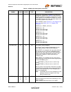
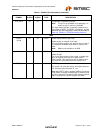
SCL/
SMBCLK/
CFG_SEL0
24 31 I/OSD12 Serial Clock (SCL)
SMBus Clock (SMBCLK)
Configuration Select_SEL0: The logic state of this
multifunction pin is internally latched on the rising edge
of RESET_N (RESET_N negation), and will determine
the hub configuration method as described in Table 3.2,
"SMBus or EEPROM Interface Behavior".
HS_IND/
CFG_SEL1
25 32 I/O12 High-Speed Upstream port indictor & Configuration
Programming Select
HS_IND: High Speed Indicator for upstream port
connection speed.
The active state of the LED will be determined as
follows:
CFG_SEL1 = ‘0’,
HS_IND is active high,
CFG_SEL1 = ‘1’,
HS_IND is active low,
‘Asserted’ = Hub is connected at HS
‘Negated’ = Hub is connected at FS
CFG_SEL1: The logic state of this pin is internally
latched on the rising edge of RESET_N (RESET_N
negation), and will determine the hub configuration
method as described in Table 3.2, "SMBus or EEPROM
Interface Behavior".
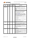
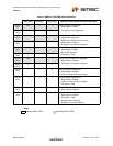
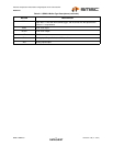
Table 3.1 USB2514 Pin Descriptions (continued)
SYMBOL 36 QFN 48 QFN
BUFFER
TYPE DESCRIPTION