


Industrial Temperature Rated USB 2.0 High-Speed 3-Port Hub Controller
Datasheet
SMSC USB2513i 33 Revision 1.98 (11-19-07)
DATASHEET
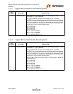
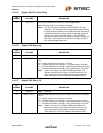
4.3.1.31 Register FFh: Status/Command
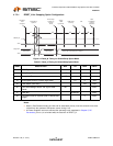
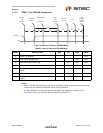
4.3.2 I2C EEPROM
The I2C EEPROM interface implements a subset of the I2C Master Specification (Please refer to the
Philips Semiconductor Standard I2C-Bus Specification for details on I2C bus protocols). The Hub’s I2C
EEPROM interface is designed to attach to a single “dedicated” I2C EEPROM, and it conforms to the
Standard-mode I2C Specification (100kbit/s transfer rate and 7-bit addressing) for protocol and
electrical compatibility.
Note: Extensions to the I2C Specification are not supported.
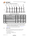
The Hub acts as the master and generates the serial clock SCL, controls the bus access (determines
which device acts as the transmitter and which device acts as the receiver), and generates the START
and STOP conditions.
4.3.2.1 Implementation Characteristics
The Hub will only access an EEPROM using the Sequential Read Protocol.
4.3.2.2 Pull-Up Resistor
The Circuit board designer is required to place external pull-up resistors (10KΩ recommended) on the
SDA/SMBDATA & SCL/SMBCLK/CFG_SELO lines (per SMBus 1.0 Specification, and EEPROM
manufacturer guidelines) to Vcc in order to assure proper operation.
4.3.2.3 I2C EEPROM Slave Address
Slave address is 1010000.
Note: 10-bit addressing is NOT supported.
4.3.3 In-Circuit EEPROM Programming
The EEPROM can be programmed via ATE by pulling RESET_N low (which tri-states the Hub’s
EEPROM interface and allows an external source to program the EEPROM).
BIT
NUMBER BIT NAME DESCRIPTION
7:3 Reserved Reserved
2 INTF_PW_DN SMBus Interface Power Down
‘0’ = Interface is active
‘1’ = Interface power down after ACK has completed
1 RESET Reset the SMBus Interface and internal memory back to RESET_N
assertion default settings.
‘0’ = Normal Run/Idle State
‘1’ = Force a reset of registers to their default state
0 USB_ATTACH USB Attach (and write protect)
‘0’ = SMBus slave interface is active
‘1’ = Hub will signal a USB attach event to an upstream device, and the
internal memory (address range 00h-FEh) is “write-protected” to prevent
unintentional data corruption.