


12
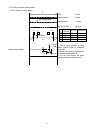
3.3 Connector connections
1) J1 Power input
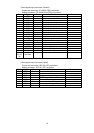
2) CN2 Connect to printer mechanism (head)
3) CN3 Connect to printer mechanism (motor)
4) CN4 Connect to printer mechanism (sensors)
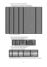
5) CN5 Data signal input
6) CN6 Connect to autocutter
7) CN7 Connect to auxiliary sensor(paper low end)
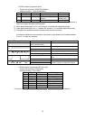
8) CN8 Connect to operation panel
9) CN9 Connect to presenter (NPT-301 only)
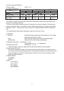
3.4 Connector signal details
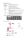
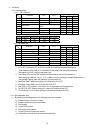
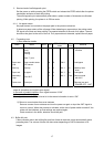
1.J1 power input connecter (D type)
Printer side connector : B4B-XHA (JST)
Mating connector : XHP-4 (JST)
Pin # Signal name Input/Output Function
1 VH Input Power DC +24V
2 VH Input Power DC +24V
3 GND - Power GND
4 GND - Power GND
* A sufficient volume of power supply is required to maintain print quality due to high peak
current that may run according to printing. If power supply cable is excessively long, the
operation may become unstable. Cable should be as short as possible. If not available,
connect cables near the printer and place an electrolysis condenser of 2200 between
power supply and ground. Voltage resistance should be higher than 35V. Make sure to
connect FG wire to prevent from ESD problems.
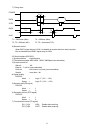
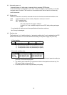
2. Power input connecter (P type, R type)
Printer side connector : TCS7960-532010 (Hoshiden)
Mating connector : TCP8927-53-1100, TCP8935-53-1100 (Hoshiden) Equivalent
Pin # Signal name Input/Output Function
1 VH Input Power DC +24V
2 GND - Power ground
3 Not available -
Shell FG - FG
* A sufficient volume of power supply is required to maintain print quality due to high peak
current that may run according to printing. If power supply cable is excessively long, the
operation may become unstable. Cable should be as short as possible. If not available,
connect cables near the printer and place an electrolysis condenser of 2200 between
power supply and ground. Voltage resistance should be higher than 35V. Make sure to
connect FG wire to prevent from ESD problems.